Functional diagram – Rainbow Electronics MAX6649 User Manual
Page 14
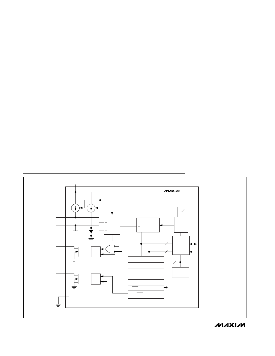
MUX
REMOTE
LOCAL
ADC
2
CONTROL
LOGIC
SMBus
READ
WRITE
8
8
ADDRESS
DECODER
7
S
R
Q
DIODE
FAULT
DXP
DXN
SCLK
SDA
REGISTER BANK
COMMAND BYTE
REMOTE TEMPERATURE
LOCAL TEMPERATURE
ALERT THRESHOLD
ALERT RESPONSE ADDRESS
V
CC
S
R
Q
OVERT
GND
ALERT
MAX6646/MAX6647/MAX6649
OVERT THRESHOLD
Functional Diagram
MAX6646/MAX6647/MAX6649
When measuring the temperature of a CPU or other IC
with an on-chip sense junction, thermal mass has virtu-
ally no effect; the measured temperature of the junction
tracks the actual temperature within a conversion cycle.
When measuring temperature with discrete remote sen-
sors, smaller packages, such as SC70s or SOT23s,
yield the best thermal response times. Take care to
account for thermal gradients between the heat source
and the sensor, and ensure that stray air currents
across the sensor package do not interfere with mea-
surement accuracy.
Self-heating does not significantly affect measurement
accuracy. Remote-sensor self-heating due to the diode
current source is negligible. For the local diode, the
worst-case error occurs when autoconverting at the
fastest rate and simultaneously sinking maximum cur-
rent at the ALERT output. For example, with V
CC
=
5.0V, at a 4Hz conversion rate and with ALERT sinking
1mA, the typical power dissipation is:
5.0V x 500µA + 0.4V x 1mA = 2.9mW
ø
J-A
for the 8-pin µMAX package is +221°C/W, so
assuming no copper PC board heat sinking, the result-
ing temperature rise is:
∆T = 2.9mW x +221°C/W = +0.6409°C
Even under nearly worst-case conditions, it is difficult to
introduce a significant self-heating error.
+145°C Precision SMBus-Compatible Remote/
Local Sensors with Overtemperature Alarms
14
______________________________________________________________________________________