Initial power-up, Table 1. key-switch mapping – Rainbow Electronics MAX7359 User Manual
Page 7
MAX7359
2-Wire Interfaced Low-EMI
Key Switch Controller/GPO
_______________________________________________________________________________________
7
PIN
COL0
COL1
COL2/PORT2 COL3/PORT3 COL4/PORT4 COL5/PORT5 COL6/PORT6 COL7/PORT7
ROW0
KEY 0
KEY 8
KEY 16
KEY 24
KEY 32
KEY 40
KEY 48
KEY 56
ROW1
KEY 1
KEY 9
KEY 17
KEY 25
KEY 33
KEY 41
KEY 49
KEY 57
ROW2
KEY 2
KEY 10
KEY 18
KEY 26
KEY 34
KEY 42
KEY 50
KEY 58
ROW3
KEY 3
KEY 11
KEY 19
KEY 27
KEY 35
KEY 43
KEY 51
KEY 59
ROW4
KEY 4
KEY 12
KEY 20
KEY 28
KEY 36
KEY 44
KEY 52
KEY 60
ROW5
KEY 5
KEY 13
KEY 21
KEY 29
KEY 37
KEY 45
KEY 53
KEY 61
ROW6
KEY 6
KEY 14
KEY 22
KEY 30
KEY 38
KEY 46
KEY 54
KEY 62
ROW7
KEY 7
KEY 15
KEY 23
KEY 31
KEY 39
KEY 47
KEY 55
KEY 63
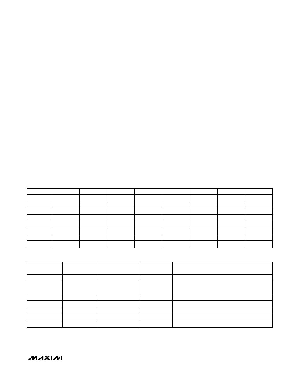
Table 1. Key-Switch Mapping
ADDRESS
CODE (hex)
READ/WRITE
POWER-UP VALUE
(hex)
REGISTER
FUNCTION
DESCRIPTION
0x00
Read only
0x3F
Keys FIFO
Read FIFO key scan data out
0x01
R/W
0x0A
Configuration
Power down, key release enable, autowakeup, and
I
2
C timeout enable
0x02
R/W
0xFF
Debounce
Key debounce time setting and GPO enable
0x03
R/W
0x00
Interrupt
INT frequency setting
0x04
R/W
0xFE
Ports
Ports 2–7 and INT GPO control
0x05
R/W
0x00
Key repeat
Delay and frequency for key repeat
0x06
R/W
0x07
Sleep
Idle time to autosleep
Table 2. Register Address Map and Power-Up Condition
Key-Scan Controller
Key inputs are scanned statically, not dynamically, to
ensure low-EMI operation. As inputs only toggle in
response to switch changes, the key matrix can be
routed closer to sensitive circuit nodes.
The key controller debounces and maintains a FIFO of
key-press and release events (including autorepeated
key presses, if autorepeat is enabled). Table 1 shows
keys order.
_____________________Initial Power-Up
On power-up, all control registers are set to power-up
values and the MAX7359 is in sleep mode (Table 2).
Registers Description
Keys FIFO Register (0x00)
The keys FIFO register contains the information pertain-
ing to the status of the keys FIFO, as well as the key
events that have been debounced (Table 3). Bits D0 to
D5 denote which of the 64 keys have been debounced
and the keys are numbered as in Table 1.
D7 indicates if there is more data in the FIFO except
when D5:D0 indicate key 63 or key 62. When D5:D0
indicate key 63 or key 62, the host should read one
more time to determine whether there is more data in
FIFO. It is better to use key 62 and key 63 for rarely
used keys. D6 indicates if it is a key-press or release
event except when D5:D0 indicate key 63 or key 62.
Reading the key-scan FIFO clears the interrupt
INT
depending on the setting of bit D5 in the configuration
register (0x01).
Configuration Register (0x01)
The configuration register controls the I
2
C bus timeout
feature, enables key release detection, enables autowake,
and determines how
INT should be deasserted. By writing
to bit D7, you can put the MAX7359 into sleep mode or
operating mode, however, autosleep and autowake,
when enabled, also change the status of this bit (Table 4).