Table 6. interrupt register format (0x03) – Rainbow Electronics MAX7359 User Manual
Page 11
MAX7359
2-Wire Interfaced Low-EMI
Key Switch Controller/GPO
______________________________________________________________________________________
11
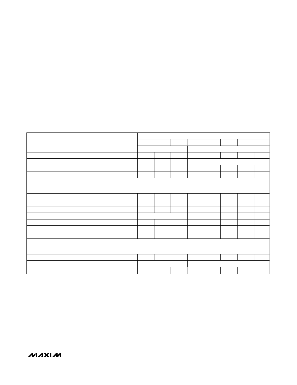
Interrupt Register (0x03)
The interrupt register contains information related to the
settings of the interrupt request function, as well as the
status of the
INT output, which can also be configured as
a GPO. If bits D0 through D7 are set to 0x00, the
INT out-
put is configured as a GPO that is controlled by bit D1 in
the port register. There are two types of interrupts, the
FIFO based-interrupt and time-based interrupt. The time-
based interrupt can be configured to assert
INT after a
number of debounce cycles. By setting bits D0 through
D4 to an appropriate value, the interrupt can be asserted
at the end of the selected number of debounce cycles
following a key event (Table 6). This number ranges from
1 to 31 debounce cycles. The FIFO based interrupt can
be configured to assert
INT when there are between 4
through 16 key events stored in the FIFO. Bits D7 through
D5 set the FIFO based interrupt. Both interrupts can be
configured simultaneously and
INT asserts depending on
which condition is met first.
INT deasserts depending on
the status of bit D5 in the configuration register.
REGISTER DATA
D7
D6
D5
D4
D3
D2
D1
D0
REGISTER DESCRIPTION
FIFO-BASED
INT
TIME-BASED
INT
INT used as GPO
0
0
0
0
0
0
0
0
FIFO based INT disabled
0
0
0
Not all zero
INT asserts every debounce cycles
0
0
0
0
0
0
0
1
INT asserts every 2 debounce cycles
0
0
0
0
0
0
1
0
.
.
.
INT asserts every 29 debounce
0
0
0
1
1
1
0
1
INT asserts every 30 debounce
0
0
0
1
1
1
1
0
INT asserts every 31 debounce
0
0
0
1
1
1
1
1
Time based INT disabled
Not all zero
0
0
0
0
0
INT asserts when FIFO has 2 key events
0
0
1
0
0
0
0
0
INT asserts when FIFO has 4 key events
0
1
0
0
0
0
0
0
INT asserts when FIFO has 6 key events
0
1
1
0
0
0
0
0
.
.
.
INT asserts when FIFO has 16 key events
1
1
1
0
0
0
0
0
Both time base and FIFO based interrupts active
Not all zero
Not all zero
Power-up default setting
0
0
0
0
0
0
0
0
Table 6. Interrupt Register Format (0x03)
Ports Register (0x04)
The ports register sets the values of ports 2 through 7 and
the
INT port when configured as open-drain GPOs. The
settings in this register are ignored for ports not config-
ured as GPOs, and a read from this register returns the
values stored in the register (Table 7).
Autorepeat Register (0x05)
The MAX7359 autorepeat feature notifies the host that at
least one key has been pressed for a continuous period
of time. The autorepeat register enables or disables this
feature, sets the time delay after the last key event before
the key repeat code (0x7E) is entered into the FIFO, and
sets the frequency at which the key repeat code is
entered into the FIFO thereafter. Bit D7 specifies whether
the autorepeat function is enabled with 0 denoting
autorepeat disabled and 1 denoting autorepeat enabled.
Bits D0 through D3 specify the autorepeat delay in terms
of debounce cycles ranging from eight debounce cycles
to 128 debounce cycles (Table 8). Bits D4 through D6
specify the autorepeat rate or frequency ranging from 4
to 32 debounce cycles.
When autorepeat is enabled, holding the key pressed
results in a key repeat event that is denoted by 0x7E. The
key being pressed does not show up again in the FIFO.