Max7359, Applications information – Rainbow Electronics MAX7359 User Manual
Page 17
MAX7359
2-Wire Interfaced Low-EMI
Key Switch Controller/GPO
______________________________________________________________________________________
17
MAX7359
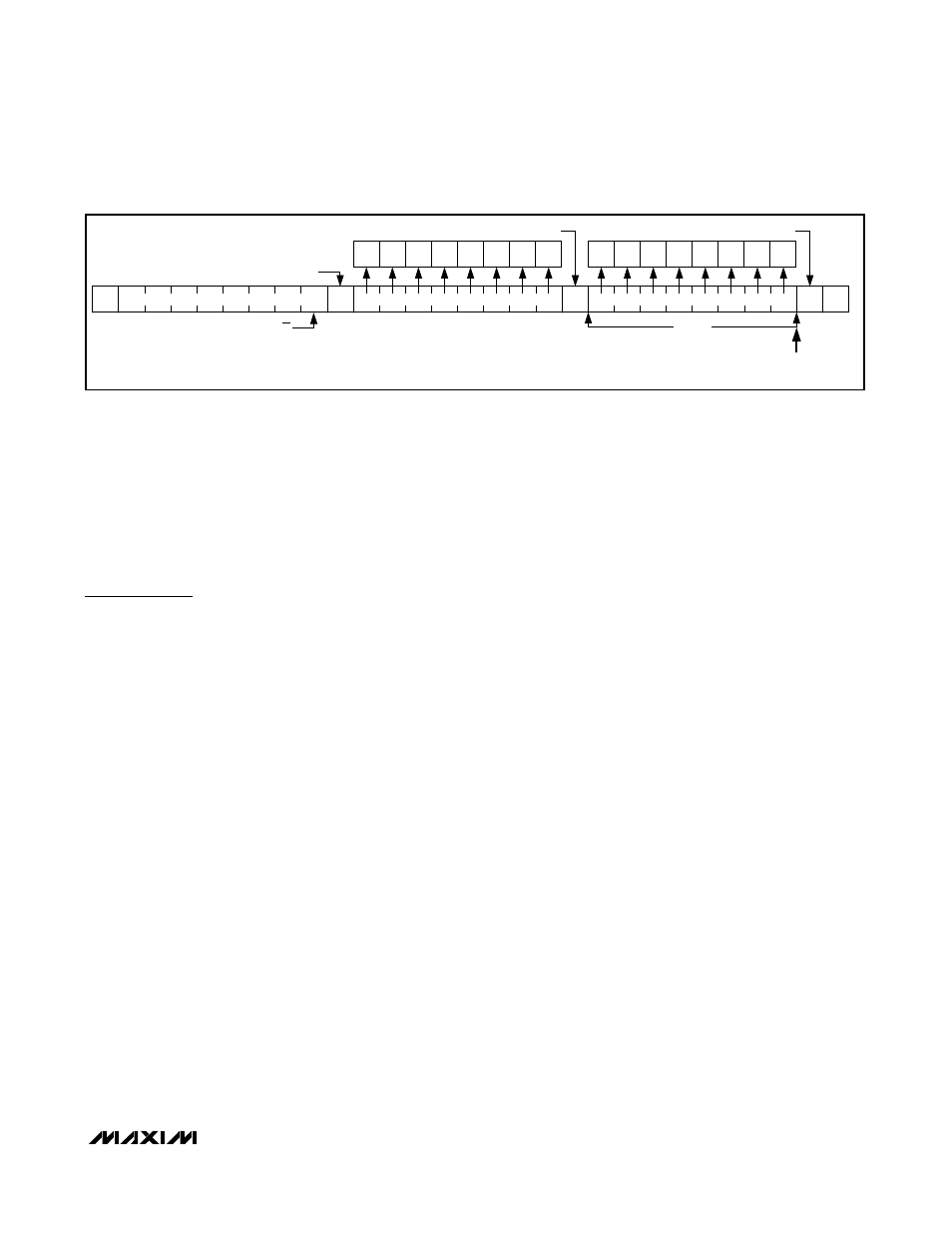
Command Address Autoincrementing
Address autoincrementing allows the MAX7359 to be
configured with fewer transmissions by minimizing the
number of times the command address needs to be
sent. The command address stored in the MAX7359
generally increments after each data byte is written or
read (Table 11). Autoincrement only works when doing
a multiburst read or write.
Applications Information
Ghost-Key Elimination
Ghost keys are a phenomenon inherent with key-switch
matrices. When three switches located at the corners of
a matrix rectangle are pressed simultaneously, the
switch that is located at the last corner of the rectangle
(the ghost key) also appears to be pressed. This occurs
because the potentials at the two sides of the ghost-key
switch are identical due to the other three connections—
the switch is electrically shorted by the combination of
the other three switches (Figure 9). Because the key
appears to be pressed electrically, it is impossible to
detect which of the four keys is the ghost key.
The MAX7359 employs a proprietary scheme that
detects any three-key combination that generates a
fourth ghost key, and does not report the third key that
causes a ghost key event. This means that although
ghost keys are never reported, many combinations of
three keys are effectively ignored when pressed at the
same time. Applications requiring three-key combina-
tions (such as ) must ensure that the
three keys are not wired in positions that define the ver-
tices of a rectangle (Figure 10). There is no limit on the
number of keys that can be pressed simultaneously as
long as the keys do not generate ghost key events and
FIFO is not full.
Low-EMI Operation
The MAX7359 uses two techniques to minimize EMI
radiating from the key-switch wiring. First, the voltage
across the switch matrix never exceeds 0.55V when not
in sleep mode, irrespective of supply voltage V
CC
. This
reduces the voltage swing at any node when a switch is
pressed to 0.55V maximum. Second, the keys are not
dynamically scanned, which would cause the key-
switch wiring to continuously radiate interference.
Instead, the keys are monitored for current draw (only
occurs when pressed), and debounce circuitry only
operates when one or more keys are actually pressed.
Power-Supply Considerations
The MAX7359 operates with a 1.62V to 3.6V power-
supply voltage. Bypass the power supply to GND with a
0.047µF or higher ceramic capacitor as close as possi-
ble to the device.
Switch On-Resistance
The MAX7359 is designed to be insensitive to resis-
tance either in the key switches or the switch routing to
and from the appropriate COLx and ROWx up to 5kΩ.
These controllers are therefore compatible with low-
cost membrane and conductive carbon switches.
S
A
A
A
P
0
SLAVE ADDRESS
COMMAND BYTE
DATA BYTE
N BYTES
AUTOINCREMENT
COMMAND BYTE ADDRESS
D7
D6
D5
D4
D3
D2
D1
D0
D1
D0
D3
D2
D5
D4
D7
D6
ACKNOWLEDGE FROM MAX7359
ACKNOWLEDGE FROM MAX73459
ACKNOWLEDGE FROM MAX7359
R/W
Figure 8. N Data Bytes Received