Applications information, Available output current calculation – Rainbow Electronics MAX15007 User Manual
Page 10
MAX15006/MAX15007
40V, Ultra-Low Quiescent-Current
Linear Regulators in 6-Pin TDFN/8-Pin SO
10
______________________________________________________________________________________
Applications Information
Available Output Current Calculation
The MAX15006/MAX15007 provide up to 50mA of con-
tinuous output current. The input voltage range extends
to 40V. Package power dissipation limits the amount of
output current available for a given input/output voltage
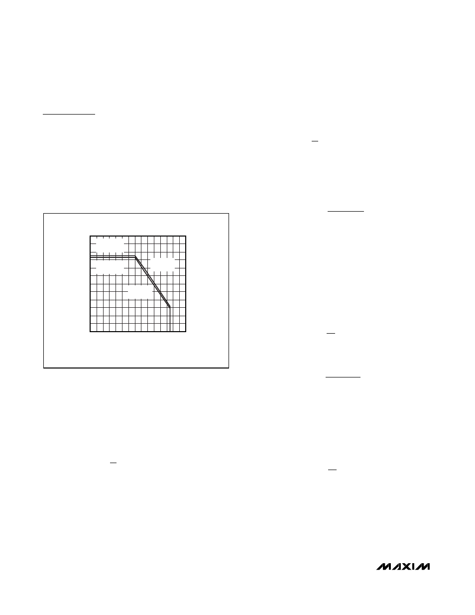
and ambient temperature. Figure 4 shows the maximum
allowable power dissipation for these devices to keep the
junction temperature below +150°C. Figure 4 assumes
that the exposed metal pad of the MAX15006/MAX15007
is soldered to 1in
2
of PCB copper.
Use Figure 4 to determine the allowable package dissi-
pation for a given ambient temperature. Alternately, use
the following formulas to calculate the allowable pack-
age dissipation. For the TDFN package:
For the SO-EP package:
After determining the allowable package dissipation,
calculate the maximum allowable output current, with-
out exceeding the +150°C junction temperature, using
the following formula:
The above equations do not include the negligible
power dissipation from self-heating due to the IC
ground current.
Example 1 (TDFN Package):
T
A
= +125°C
V
IN
= 26V
V
OUT
= 3.3V
Calculate the maximum allowable package dissipation
at the given temperature as follows:
And establish the maximum output current:
Example 2 (TDFN Package):
T
A
= +85°C
V
IN
= 14V
V
OUT
= 5V
Calculate the maximum allowable package dissipation
at the given temperature as follows:
P
1.9048W 0.0238
W
C
85 C 70 C
1.5478W
D
=
−
°
° −
°
(
)
=
I
595.8mW
26V 3.3V
26.2mA
OUT(MAX)
=
−
=
P
1.9048W 0.0238
W
C
125 C 70 C
595.8mW
D
=
−
°
° −
°
(
)
=
I
P
V
V
50mA
OUT(MAX)
D
IN
OUT
=
−
≤
P
D
.
.
.
–
=
≤ + °
−
°
°
(
)
+ °
<
≤ +
°
⎧
⎨
⎪
⎩⎪
⎫
⎬
⎪
⎭⎪
1 8605
70
1 8605
0 0233
70
70
125
W for T
C
W
W
C
x T
C for
C
T
C
A
A
A
P
D
.
.
.
–
=
≤ + °
−
°
°
(
)
+ °
<
≤ +
°
⎧
⎨
⎪
⎩⎪
⎫
⎬
⎪
⎭⎪
1 9048
70
1 9048
0 0238
70
70
125
W for T
C
W
W
C
x T
C for
C
T
C
A
A
A
MAX15006 fig04
TEMPERATURE (
°C)
P
D
(W)
140
120
100
40
60
80
20
0.2
0.4
0.6
0.8
1.0
1.2
1.4
1.6
1.8
2.0
2.2
2.4
0
0
1.9408W
(6-PIN TDFN)
1.8605W
(8-PIN SO-EP)
DERATE
23.8mW/
°C
DERATE
23.3mW/
°C
Figure 4. Calculated Maximum Power Dissipation vs. Ambient
Temperature