Applications information – Rainbow Electronics ADC0817 User Manual
Page 11
Applications Information
(Continued)
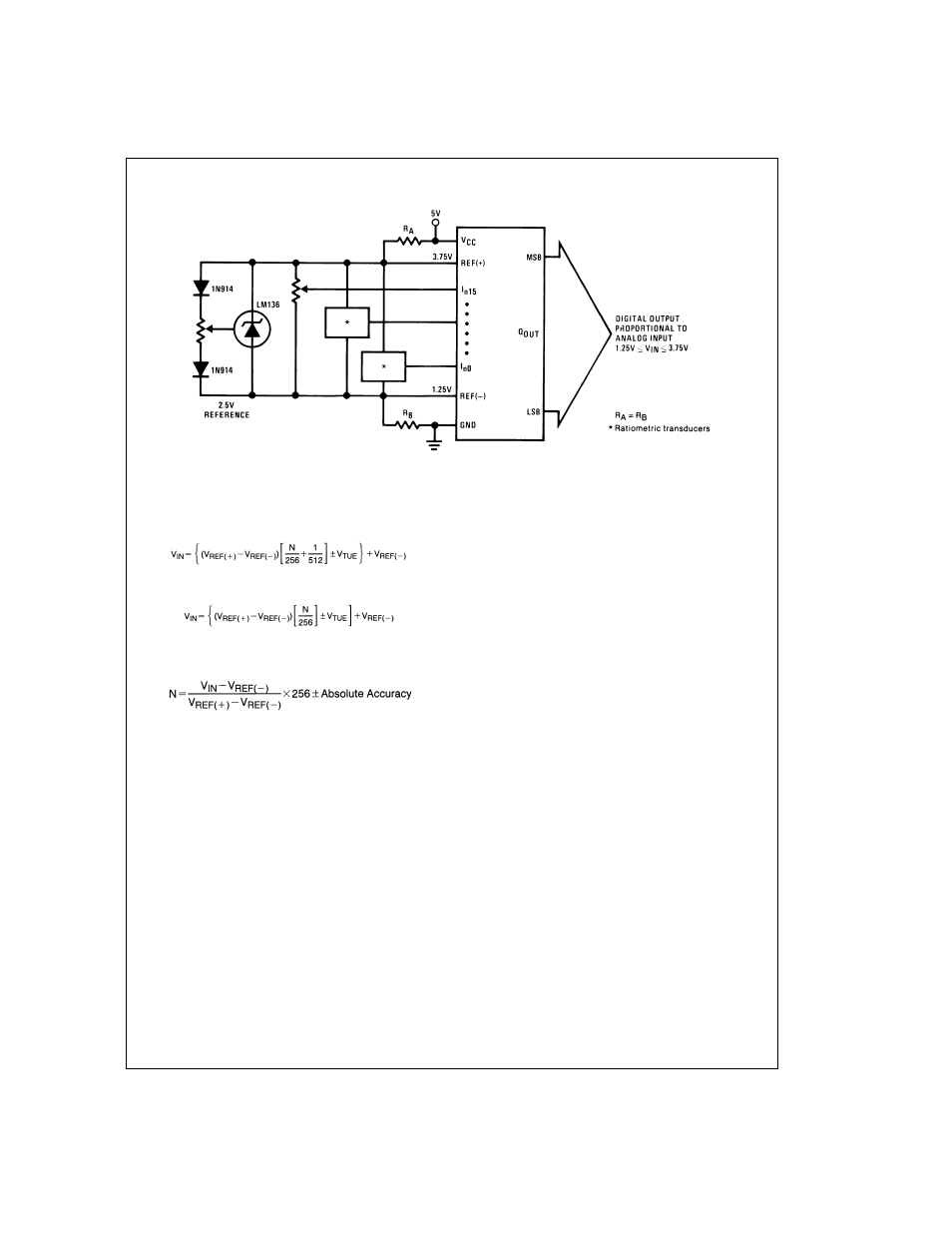
3.0 CONVERTER EQUATIONS
The transition between adjacent codes N and N + 1 is given
by:
(2)
The center of an output code N is given by:
(3)
The output code N for an arbitrary input are the integers
within the range:
(4)
where: V
IN
= Voltage at comparator input
V
REF
= Voltage at Ref(+)
V
REF
= Voltage at Ref(−)
V
TUE
= Total unadjusted error voltage (typically
V
REF
(+)
÷
512)
4.0 ANALOG COMPARATOR INPUTS
The dynamic comparator input current is caused by the pe-
riodic switching of on-chip stray capacitances These are
connected alternately to the output of the resistor ladder/
switch tree network and to the comparator input as part of
the operation of the chopper stabilized comparator.
The average value of the comparator input current varies di-
rectly with clock frequency and with V
IN
as shown in
Figure
6
.
If no filter capacitors are used at the analog or comparator in-
puts and the signal source impedances are low, the com-
parator input current should not introduce converter errors,
as the transient created by the capacitance discharge will die
out before the comparator output is strobed.
If input filter capacitors are desired for noise reduction and
signal conditioning they will tend to average out the dynamic
comparator input current. It will then take on the characteris-
tics of a DC bias current whose effect can be predicted con-
ventionally. See AN-258 for further discussion.
DS005277-15
FIGURE 13. Symmetrically Centered Reference
11
www.national.com