Electrical characteristics (continued), Table 1. insertion loss mask – Rainbow Electronics MAX4889C User Manual
Page 3
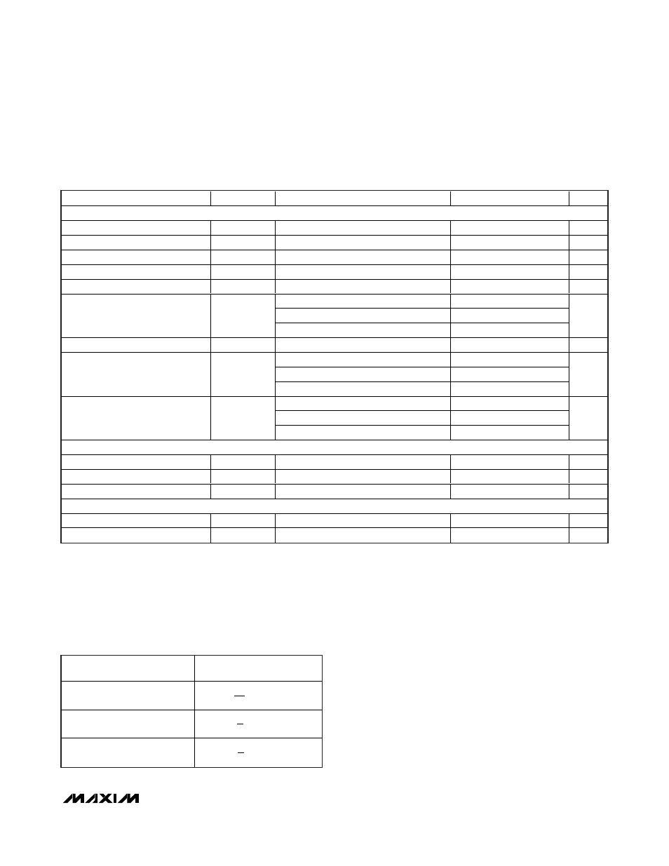
FREQUENCY RANGE
(GHz)
MAXIMUM INSERTION
LOSS (dB)
0–2.5
2.5–5
5 or greater
MAX4889B/MAX4889C
2.5/5.0Gbps PCIe Passive Switches
_______________________________________________________________________________________
3
Note 3: All units are 100% production tested at T
A
= +85°C. Limits over the operating temperature range are guaranteed by design
and characterization and are not production tested.
Note 4: ΔR
ON
= R
ON (MAX)
- R
ON (MIN)
.
Note 5: Guaranteed by design, not production tested.
Note 6: Flatness is defined as the difference between the maximum and minimum value of on-resistance as measured over the specified
analog signal range.
ELECTRICAL CHARACTERISTICS (continued)
(V
CC
= +3.3V ±10%, T
A
=T
MIN
to T
MAX,
unless otherwise noted. Typical values are at V
CC
= +3.3V, T
A
= +25°C, unless otherwise
noted.) (Note 3)
PARAMETER
SYMBOL
CONDITIONS
MIN
TYP
MAX
UNITS
AC PERFORMANCE
SEL-to-Switch Turn-On Time
t
ON_SEL
Z
S
= Z
L
= 50
Ω
80
ns
SEL-to-Switch Turn-Off Time
t
OFF_SEL
Z
S
= Z
L
= 50
Ω, Figure 1
15
ns
Propagation Delay
t
PD
Z
S
= Z
L
= 50
Ω, Figure 2
50
ps
Output Skew Between Pairs
t
SKEW1
Z
S
= Z
L
= 50
Ω, Figure2
50
ps
Output Skew Between Same Pair
t
SKEW2
Z
S
= Z
L
= 50
Ω, Figure 2
10
ps
0Hz < f
≤ 2.8GHz
-14
2.8GHz < f
≤ 5.0GHz
-8
Differential Return Loss (Note 5)
S
DD11
f > 5.0GHz
-3
dB
Differential Insertion Loss (Note 5)
S
DD21
See Table 1
dB
0Hz < f
≤ 2.5GHz
-40
2.5GHz < f
≤ 5.0GHz
-30
Differential Crosstalk (Note 5)
S
DDCTK
f > 5.0GHz
-25
dB
0Hz < f
≤ 2.5GHz
-15
2.5GHz < f
≤ 5.0GHz
-12
Differential Off-Isolation (Note 5)
S
DD21_OFF
f > 5.0GHz
-12
dB
CONTROL INPUT (SEL)
Input Logic High
V
IH
1.4
V
Input Logic Low
V
IL
0.6
V
Input Logic Hysteresis
V
HYST
130
mV
POWER SUPPLY
Power-Supply Range
V
CC
3.0
3.6
V
V
CC
Supply Current
I
CC
V
SEL
= 0 or V
CC
1
mA
Table 1. Insertion Loss Mask
1
5
f
+ 0.6
GHz
4
2
×
5
f
- 1.0
GHz
6 ×
5
f
- 3.0
GHz
8 Ч