Rainbow Electronics MAX5480 User Manual
Page 6
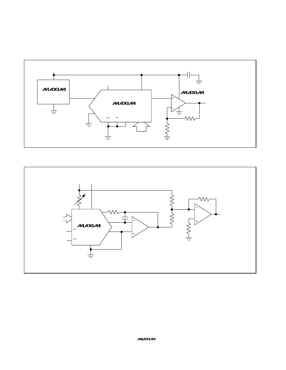
MAX5480
8-Bit Parallel DAC in
QSOP-16 Package
MAX5480
MAX4330
MAX6120
+1.2V
0V
≤
V
OUT
≤
2.4V (255/256)
0.1
µ
F
OUT1
3
16
14
15
12
13
2
1
10k
10k
REF
OUT2
RFB
V
DD
V
OUT
V
IN
N.C.
+5V
GND
GND
D7–D0
4–11
DATA IN
CS
WR
Figure 5. Single-Supply Voltage-Output Mode (Buffered)
MAX5480
C1
16
14
15
0 TO -V
REF
V
REF
±10V
(AC OR DC)
V
DD
R2
1k
Ω
R1
2k
Ω
OUT1
OUT2
NOTES:
1. ADJUST R1 FOR V
OUT
= 0V AT CODE 10000000.
2. C1 PHASE COMPENSATION (10pF to 15pF) MAY BE
REQUIRED IF A1 IS A HIGH-SPEED AMPLIFIER.
REF
RFB
GND
3
2
1
GND
V
DD
A1
1/2 MXL1013
A1
1/2 MXL1013
V
OUT
R5
20k
Ω
R3
20k
Ω
R4
10k
Ω
R6
5k
Ω
D7–D0
12
DATA
INPUTS 4–11
13
WR
CS
Figure 6. Bipolar (Four-Quadrant) Operation
Maxim cannot assume responsibility for use of any circuitry other than circuitry entirely embodied in a Maxim product. No circuit patent licenses are
implied. Maxim reserves the right to change the circuitry and specifications without notice at any time.
6
_____________________Maxim Integrated Products, 120 San Gabriel Drive, Sunnyvale, CA 94086 408-737-7600
© 1997 Maxim Integrated Products
Printed USA
is a registered trademark of Maxim Integrated Products.