Ac electrical characteristics: 3-wire interface, Ac electrical characteristics: spi interface, Ac electrical characteristics: eeprom – Rainbow Electronics MAX31723 User Manual
Page 3
MAX31722/MAX31723
Digital Thermometers and Thermostats
with SPI/3-Wire Interface
3
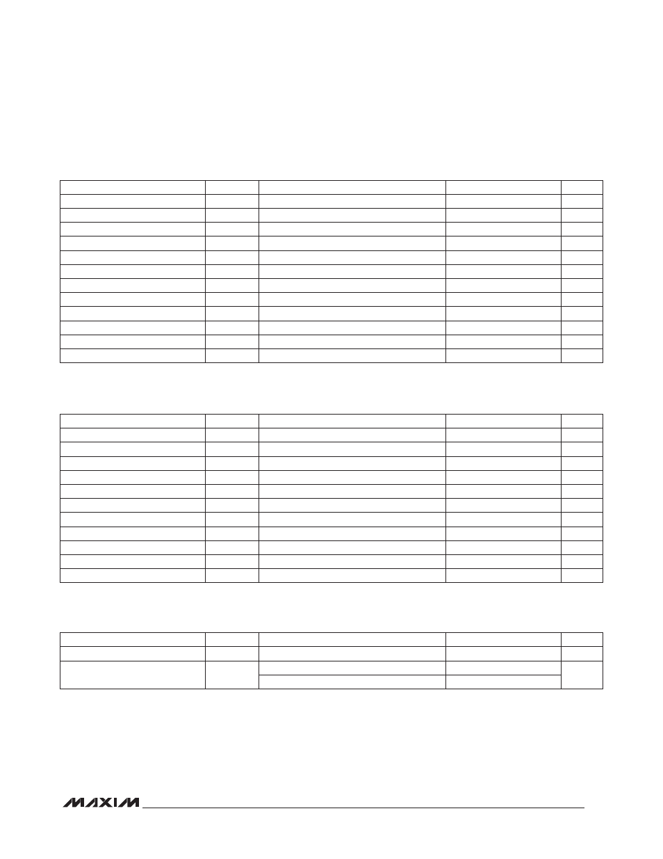
AC ELECTRICAL CHARACTERISTICS: 3-WIRE INTERFACE
(V
DD
= 1.7V to 3.7V, T
J
= -55NC to +125NC, unless otherwise noted.) (Figures 1, 2)
AC ELECTRICAL CHARACTERISTICS: SPI INTERFACE
(V
DD
= 1.7V to 3.7V, T
J
= -55NC to +125NC, unless otherwise noted.) (Figures 3, 4)
AC ELECTRICAL CHARACTERISTICS: EEPROM
(V
DD
= 1.7V to 3.7V, T
J
= -55NC to +125NC, unless otherwise noted.)
Note 1: All voltages are referenced to ground. Currents entering the IC are specified positive, and currents exiting the IC are negative.
Note 2: Logic 0 voltages are specified at a sink current of 3mA.
Note 3: Logic 1 voltages are specified at a source current of 1mA.
Note 4: I
CC
specified with SCLK = V
DD
and CE = GND.
Note 5: Measured at V
IH
= 0.7V x V
DD
or V
IL
= 0.3 x V
DD
and 10ms maximum rise and fall times.
Note 6: Measured with 50pF load.
Note 7: Measured at V
OH
= 0.7 x V
DD
or V
OL
= 0.3 x V
DD
. Measured from the 50% point of SCLK to the V
OH
minimum of SDO.
Note 8: V
DD
must be > 2.0V during EEPROM write cycles.
PARAMETER
SYMBOL
CONDITIONS
MIN
TYP
MAX
UNITS
Data to SCLK Setup
t
DC
(Notes 5, 6)
35
ns
SCLK to Data Hold
t
CDH
(Notes 5, 6)
35
ns
SCLK to Data Valid
t
CDD
(Notes 5, 6, 7)
80
ns
SCLK Low Time
t
CL
(Note 6)
100
ns
SCLK High Time
t
CH
(Note 6)
100
ns
SCLK Frequency
t
CLK
(Note 6)
DC
5.0
MHz
SCLK Rise and Fall
t
R
, t
F
200
ns
CE to SCLK Setup
t
CC
(Note 6)
400
ns
SCLK to CE Hold
t
CCH
(Note 6)
100
ns
CE Inactive Time
t
CWH
(Note 6)
400
ns
CE to Output High-Z
t
CDZ
(Notes 5, 6)
40
ns
PARAMETER
SYMBOL
CONDITIONS
MIN
TYP
MAX
UNITS
EEPROM Write Cycle Time
t
WR
-40NC to +85NC (Note 8)
15
ms
EEPROM Write Endurance
N
EEWR
-40NC P T
A
P +85NC (Note 8)
20,000
Cycles
T
A
= +25NC (Note 8)
80,000
PARAMETER
SYMBOL
CONDITIONS
MIN
TYP
MAX
UNITS
Data to SCLK Setup
t
DC
(Notes 5, 6)
35
ns
SCLK to Data Hold
t
CDH
(Notes 5, 6)
35
ns
SCLK to Data Valid
t
CDD
(Notes 5, 6, 7)
80
ns
SCLK Low Time
t
CL
(Note 6)
100
ns
SCLK High Time
t
CH
(Note 6)
100
ns
SCLK Frequency
t
CLK
(Note 6)
DC
5.0
MHz
SCLK Rise and Fall
t
R
, t
F
200
ns
CE to SCLK Setup
t
CC
(Note 6)
400
ns
SCLK to CE Hold
t
CCH
(Note 6)
100
ns
CE Inactive Time
t
CWH
(Note 6)
400
ns
CE to Output High-Z
t
CDZ
(Notes 5, 6)
40
ns
SCLK to Output High-Z
t
CCZ
(Notes 5, 6)
40
ns