Rainbow Electronics MAX4329 User Manual
Page 10
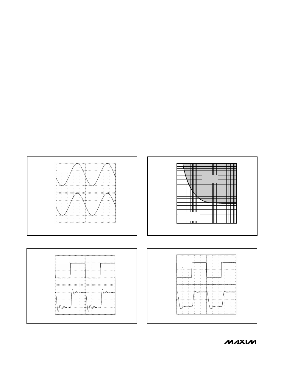
Figure 3. Rail-to-Rail Input /Output Voltage Range
Figure 4. Capacitive-Load Stability
MAX4322/MAX4323/MAX4326/MAX4327/MAX4329
Single/Dual/Quad, Low-Cost, SOT23,
Low-Power, Rail-to-Rail I/O Op Amps
10
______________________________________________________________________________________
IN
TIME (400ns/div)
VOLTAGE (50mV/div)
OUT
A
V
= +1
C
L
= 500pF
Figure 5. Small-Signal Transient Response with
Capacitive Load
IN
TIME (400ns/div)
VOLTAGE (50mV/div)
OUT
A
V
= +1
C
L
= 1000pF
R
S
= 39
Ω
Figure 6. Transient Response to Capacitive Load with
Isolation Resistor
IN
TIME (2
µs/div)
VOLTAGE (1V/div)
OUT
V
CC
= 3V
A
V
= +1
10,000
100
100
1k
100k
10k
RESISTIVE LOAD (
Ω)
CAPACITIVE LOAD (pF)
1000
UNSTABLE
REGION
R
L
TO V
EE
V
OUT
= V
CC
/2
Power-Up and Shutdown Mode
The MAX4322/MAX4323/MAX4326/MAX4327/MAX4329
amplifiers typically settle within 1µs after power-up.
Using the test circuit of Figure 8, Figures 9 and 10 show
the output voltage and supply current on power-up.
The MAX4323 and MAX4327 have a shutdown option.
When the shutdown pin (SHDN) is pulled low, the sup-
ply current drops below 25µA per amplifier and the
amplifiers are disabled with the outputs in a high-
impedance state. Pulling SHDN high or leaving it float-
ing enables the amplifier. In the dual-amplifier
MAX4327, the shutdown functions operate indepen-
dently. Figures 11 and 12 show the output voltage and
supply current responses of the MAX4323 to a shut-
down pulse.
Power Supplies and Layout
The MAX4322/MAX4323/MAX4326/MAX4327/MAX4329
operate from a single +2.4V to +6.5V power supply, or
from dual supplies of ±1.2V to ±3.25V. For single-supply
operation, bypass the power supply with a 0.1µF
ceramic capacitor in parallel with at least 1µF. For dual
supplies, bypass each supply to ground.
Good layout improves performance by decreasing the
amount of stray capacitance at the op amp’s inputs
and outputs. To decrease stray capacitance, minimize
trace lengths and resistor leads by placing external
components close to the op amp’s pins.