Electrical characteristics (continued) – Rainbow Electronics MAX14523C User Manual
Page 3
MAX14523A/MAX14523AL/MAX14523B/MAX14523C
250mA to 1.5A, Adjustable
Current-Limit Switches
_______________________________________________________________________________________
3
PARAMETER
SYMBOL
CONDITIONS
MIN
TYP
MAX
UNITS
FLAG OUTPUT
FLAG Output Logic-Low Voltage
I
SINK
= 1mA
0.4
V
FLAG Output Leakage Current
V
IN
= V
FLAG
= 5.5V,
FLAG deasserted
1
μA
DYNAMIC
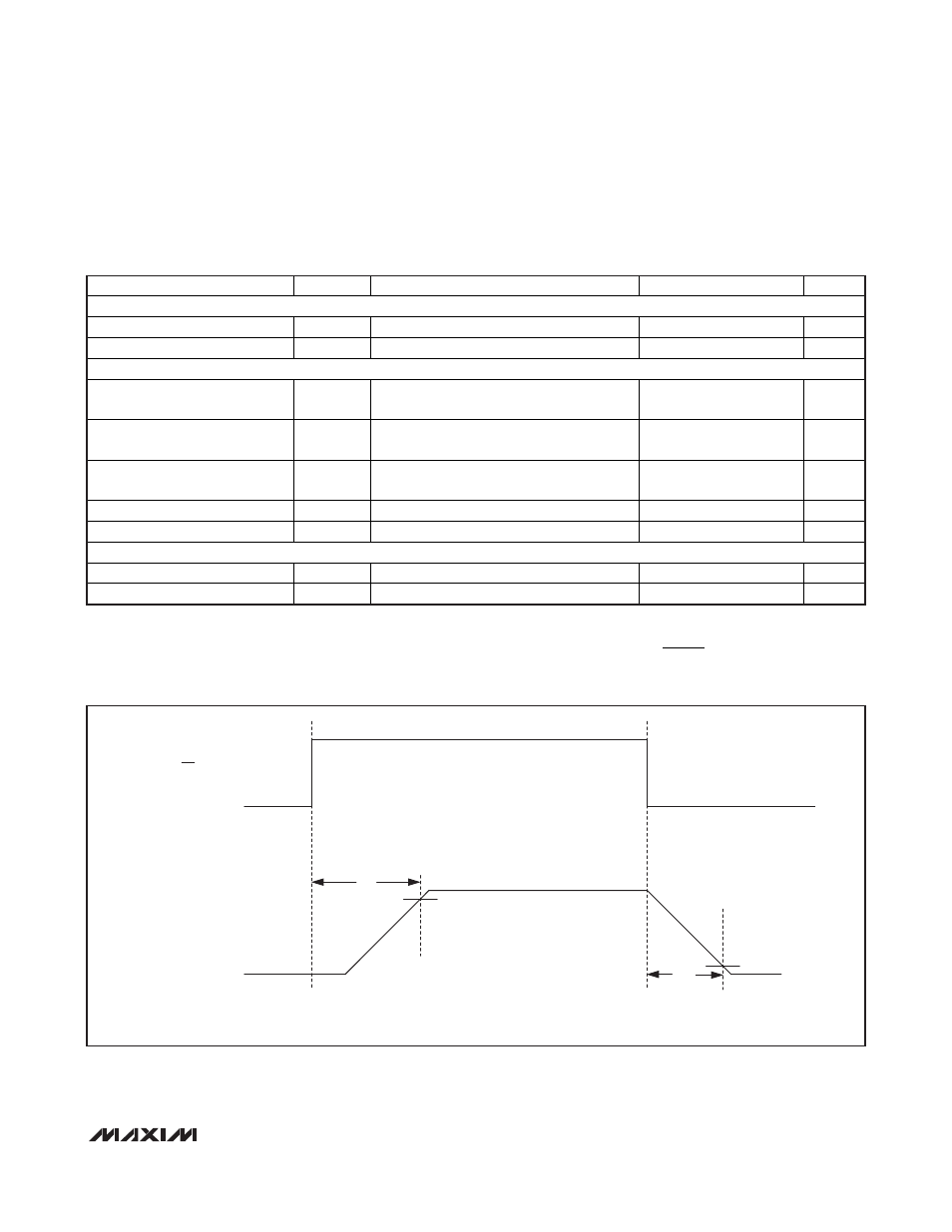
Turn-On Time
t
SS
Time from ENABLE signal to V
OUT
= 90%
of V
IN
= 3.3V, Figure 1
1
ms
Turn-Off Time
t
OFF
Time from DISABLE signal to V
OUT
= 10%
of V
IN
= 3.3V, R
L
= 20
, Figure 1
250 μs
Current-Limit Reaction Time
t
LIM
V
IN
= 3.3V, R
SETI
= 91.78k
to 563.12k,
output high and then short-circuit applied
3
μs
Blanking Time
t
BLANK
(Note 3)
10
14.5
25
ms
Retry Time
t
RETRY
MAX14523A/MAX14523AL (Note 3)
320
875
ms
THERMAL PROTECTION
Thermal
Shutdown
Low-to-high
+170 °C
Thermal Shutdown Hysteresis
15
°C
ELECTRICAL CHARACTERISTICS (continued)
(V
IN
= +1.7V to +5.5V, R
SETI
= 94.2k
Ω, C
IN
= C
OUT
= 1µF, and T
A
= T
J
= -40°C to +125°C, unless otherwise noted. Typical values
are at V
IN
= +3.3V, T
A
= +25°C.) (Note 2)
Note 2: All devices are 100% tested at 125°C. Electrical limits across the full temperature range are guaranteed by design and correlation.
Note 3: Blanking time and retry time are generated by the same oscillator. Therefore, the ratio of
is a constant value of 32.
See Figures 2 and 3.
t
t
RETRY
BLANK
t
SS
t
OFF
V
OUT
10% V
IN
90% V
IN
ON(ON)*
*( ) THE POLARITY OF THE SIGNAL IS REVERSED FOR THE MAX14523AL ONLY.
Figure 1. Timing Diagram for Measuring Turn-On Time (t
SS
) and Turn-Off Time (t
OFF
)