Max5550, Pin configuration chip information – Rainbow Electronics MAX5550 User Manual
Page 14
MAX5550
Power Sequencing
Ensure that the voltage applied to REFIN does not
exceed V
DD
at any time. If proper power sequencing is
not possible, connect an external Schottky diode
between REFIN and V
DD
to ensure compliance with the
absolute maximum ratings.
Power-Supply Bypassing and Ground
Management
Digital or AC transient signals on GND create noise at
the analog output. Return GND to the highest quality
ground plane available. For extremely noisy environ-
ments, bypass REFIN and V
DD
to GND with 1µF and
0.1µF capacitors with the 0.1µF capacitor as close to
the device as possible. Careful PC board ground layout
minimizes crosstalk between the DAC outputs and
digital inputs.
Dual, 10-Bit, Programmable, 30mA
High-Output-Current DAC
14
______________________________________________________________________________________
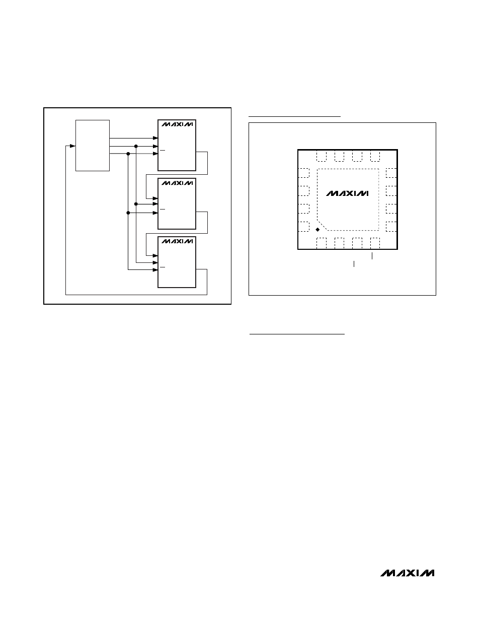
CONTROLLER
DEVICE
DIN(0)
DOUT(0)
SCLK
CS
MAX5550
DIN(1)
DOUT(1)
SCLK
CS
MAX5550
DIN(2)
DOUT(2)
SCLK
CS
MAX5550
Figure 8. Daisy-Chain Configuration
15
16
14
13
5
6
7
CS/AO
SPI/I2C
8
SCLK/SCL
FSADJB
OUTB
OUTA
1
3
V
DD
4
12
10
9
N.C.
GND
GND
REFIN
N.C.
DOUT/A1
MAX5550
DIN/SDA
FSADJA
2
11
N.C.
THIN QFN (3mm x 3mm)
TOP VIEW
Pin Configuration
Chip Information
PROCESS: BiCMOS