Pin description – Rainbow Electronics MAX6971 User Manual
Page 6
MAX6971
16-Port, 36V Constant-Current LED Driver
6
_______________________________________________________________________________________
Pin Description
PIN
NAME
FUNCTION
1
GND
Ground
2
DIN
Serial-Data Input. Data is loaded into the internal 16-bit shift register on CLK’s rising edge.
3
CLK
Serial-Clock Input. Data is loaded into the internal 16-bit shift register on CLK’s rising edge.
4
LE
Load - E nab l e Inp ut. D ata i s l oad ed tr ansp ar entl y fr om the i nter nal shi ft r eg i ster ( s) to the outp ut l atch( es)
w hi l e LE i s hi g h. D ata i s l atched i nto the outp ut l atch( es) on LE ’ s fal l i ng ed g e, and r etai ned w hi l e LE i s l ow .
5–20
OUT0–OUT15
LED Driver Outputs. OUT0 to OUT15 are open-drain, constant-current-sinking outputs rated to 28V.
21
OE
Output-Enable Input. High forces outputs OUT0 to OUT15 high impedance, without altering the contents
of the output latches. Low enables outputs OUT0 to OUT15 to follow the state of the output latches.
22
DOUT
Serial-Data Output. Data is clocked out of the 16-bit internal shift register to DOUT on CLK’s rising edge.
23
SET
LED Current Setting. Connect SET to GND through a resistor (R
SET
) to set the maximum LED current.
24
V+
Positive Supply Voltage. Bypass V+ to GND with a 0.1µF ceramic capacitor.
SERIAL-TO-PARALLEL SHIFT REGISTER
LATCHES
OUT0
OUT1
OUT2
DOUT
DIN
CLK
OUT15
CONSTANT-CURRENT SINKS
OUT3
OUT4
POWER-ON
RESET
V+
CURRENT
REFERENCE
OE
GND
GND
LE
D0
D15
D0
D15
D0
D15
R
SET
MAX6971
V+
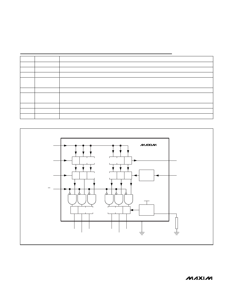
Figure 1. Block Diagram