Pin description, Typical operating characteristics (continued) – Rainbow Electronics MAX9814 User Manual
Page 6
MAX9814
Microphone Amplifier with AGC and
Low-Noise Microphone Bias
6
_______________________________________________________________________________________
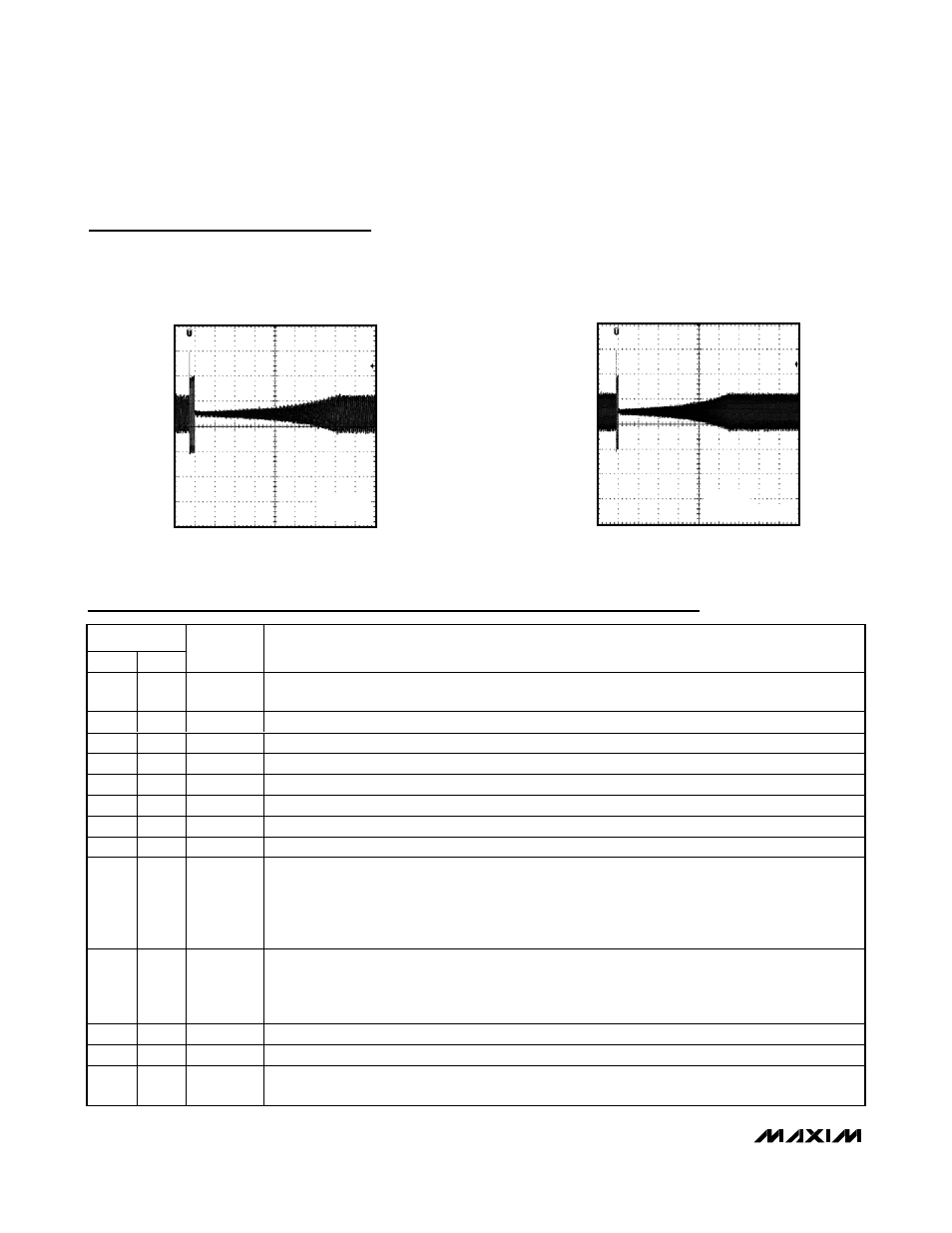
HOLD AND RELEASE TIME
MAX9814 toc19
40ms/div
V
MICOUT
500mV/div
C
CT
= 47nF
A/R = V
DD
0V
HOLD AND RELEASE TIME
MAX9814 toc20
100ms/div
V
MICOUT
500mV/div
C
CT
= 47nF
A/R = UNCONNECTED
0V
Pin Description
PIN
TDFN
UCSP
NAME
FUNCTION
1
A1
CT
Timing Capacitor Connection. Connect a capacitor to CT to control the Attack and Release times of
the AGC.
2
B2
SHDN
Active-Low Shutdown Control
3
A2
CG
Amplifier DC Offset Adjust. Connect a 2.2µF capacitor to GND to ensure zero offset at the output.
4, 11
—
N.C.
No Connection. Connect to GND.
5
A3
V
DD
Power Supply. Bypass to GND with a 1µF capacitor.
6
A4
MICOUT
Amplifier Output
7
B4
GND
Ground
8
C4
MICIN
Microphone Noninverting Input
9
B3
A/R
Tri-Level Attack and Release Ratio Select. Controls the ratio of attack time to release time for the AGC
circuit.
A/R = GND: Attack/Release Ratio is 1:500
A/R = V
DD
: Attack/Release Ratio is 1:2000
A/R = BIAS: Attack/Release Ratio is 1:4000
10
C3
GAIN
Tri-Level Amplifier Gain Control.
GAIN = V
DD
, gain set to 40dB.
GAIN = GND, gain set to 50dB.
GAIN = Unconnected, uncompressed gain set to 60dB.
12
C2
BIAS
Amplifier Bias. Bypass to GND with a 0.47µF capacitor.
13
C1
MICBIAS
Microphone Bias Output
14
B1
TH
AGC Threshold Control. TH voltage sets gain control threshold. Connect TH to MICBIAS to disable
the AGC.
Typical Operating Characteristics (continued)
(V
DD
= 5V, C
CT
= 470nF, C
CG
= 2.2µF, V
TH
= V
MICBIAS
x 0.4, GAIN = V
DD
(40dB), AGC disabled, no load, R
L
= 10kΩ, C
OUT
= 1µF,
T
A
= +25°C, unless otherwise noted.)