Rainbow Electronics MAX6642 User Manual
Page 7
When a conversion is complete, the main temperature
register and the extended temperature register are
updated.
Alarm Threshold Registers
Two registers store ALERT threshold values—one each
for the local and remote channels. If either measured
temperature equals or exceeds the corresponding
ALERT threshold value, the ALERT interrupt asserts
unless the ALERT bit is masked.
The power-on-reset (POR) state of the local ALERT
T
HIGH
register is +70
°C (0100 0110). The POR state of
the remote ALERT T
HIGH
register is +120
°C (0111 1000).
Diode Fault Detection
A continuity fault detector at DXP detects an open cir-
cuit on DXP, or a DXP short to V
CC
or GND. If an open
or short circuit exists, the external temperature register
is loaded with 1111 1111 and status bit 2 (OPEN) of the
status byte is set to 1. Immediately after POR, the sta-
tus register indicates that no fault is present. If a fault is
present upon power-up, the fault is not indicated until
the end of the first conversion. Diode faults do not set
the ALERT output.
ALERT
Interrupts
The ALERT interrupt occurs when the internal or external
temperature reading exceeds a high temperature limit
(user programmed). The ALERT interrupt output signal is
latched and can be cleared only by reading the status
register after the fault condition no longer exists or by
successfully responding to the alert response address. If
the ALERT is cleared by responding to the alert
response address and the temperature fault condition
still exists, ALERT is reasserted after the next tempera-
ture-monitoring cycle. To clear ALERT while the tempera-
ture is above the trip threshold, write a new high limit that
is higher than the current temperature. The ALERT out-
put is open drain, allowing multiple devices to share a
common interrupt line.
Alert Response Address
The SMBus alert response interrupt pointer provides
quick fault identification for simple slave devices like
temperature sensors. Upon receiving an ALERT inter-
rupt signal, the host master can broadcast a Receive
Byte transmission to the alert response slave address
MAX6642
±1°C, SMBus-Compatible Remote/Local
Temperature Sensor with Overtemperature Alarm
_______________________________________________________________________________________
7
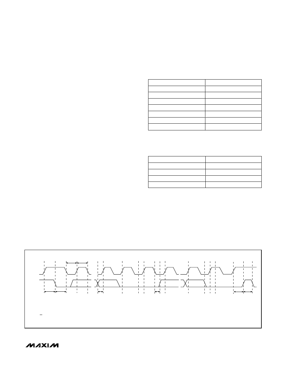
SMBCLK
A
B
C
D
E
F
G
H
I
J
K
SMBDATA
t
SU:STA
t
HD:STA
t
LOW
t
HIGH
t
SU:DAT
t
HD:DAT
t
SU:STO
t
BUF
A = START CONDITION
B = MSB OF ADDRESS CLOCKED INTO SLAVE
C = LSB OF ADDRESS CLOCKED INTO SLAVE
D = R/W BIT CLOCKED INTO SLAVE
E = SLAVE PULLS SMBDATA LINE LOW
L
M
F = ACKNOWLEDGE BIT CLOCKED INTO MASTER
G = MSB OF DATA CLOCKED INTO MASTER
H = LSB OF DATA CLOCKED INTO MASTER
I = MASTER PULLS DATA LINE LOW
J = ACKNOWLEDGE CLOCKED INTO SLAVE
K = ACKNOWLEDGE CLOCK PULSE
L = STOP CONDITION
M = NEW START CONDITION
Figure 3. SMBus Read Timing Diagram
TEMP (
°C)
DIGITAL OUTPUT
130.00
1 000 0010
127.00
0 111 1111
126.00
0 111 1110
25
0 001 1001
0.00
0 000 0000
<0.00
0 000 0000
Diode fault (short or open)
1 111 1111
Table 1. Main Temperature Register
(High Byte) Data Format
FRACTIONAL TEMP (°C)
DIGITAL OUTPUT
0.000
00XX XXXX
0.250
01XX XXXX
0.500
10XX XXXX
0.750
11XX XXXX
Table 2. Extended Resolution
Temperature Register (Low Byte) Data
Format