Max6642, Chip information, Functional diagram – Rainbow Electronics MAX6642 User Manual
Page 12: Pin configuration
MAX6642
tracks the actual temperature within a conversion cycle.
When measuring temperature with discrete remote sen-
sors, smaller packages, such as SOT23s, yield the best
thermal response times. Take care to account for ther-
mal gradients between the heat source and the sensor,
and ensure that stray air currents across the sensor
package do not interfere with measurement accuracy.
Self-heating does not significantly affect measurement
accuracy. Remote-sensor self-heating due to the diode
current source is negligible. For the local diode, the
worst-case error occurs when autoconverting at the
fastest rate and simultaneously sinking maximum cur-
rent at the ALERT output. For example, with V
CC
=
+5.0V, at an 8Hz conversion rate and with ALERT sink-
ing 1mA, the typical power dissipation is:
5.0V x 450µA + 0.4V x 1mA = 2.65mW
ø
J-A
for the 6-pin TDFN package is about +41°C/W, so
assuming no copper PC board heat sinking, the result-
ing temperature rise is:
∆T = 2.65mW x 41°C/W = +0.11°C
Even under nearly worst-case conditions, it is difficult to
introduce a significant self-heating error.
Chip Information
TRANSISTOR COUNT: 7744
PROCESS: BiCMOS
±1°C, SMBus-Compatible Remote/Local
Temperature Sensor with Overtemperature Alarm
12
______________________________________________________________________________________
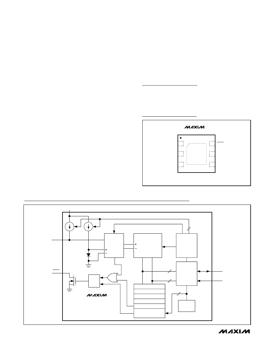
Functional Diagram
MAX6642
MUX
REMOTE
LOCAL
ADC
2
CONTROL
LOGIC
SMBus
READ
WRITE
8
8
ADDRESS
DECODER
7
S
R
Q
DXP
SCLK
SDA
REGISTER BANK
COMMAND BYTE
REMOTE TEMPERATURE
LOCAL TEMPERATURE
ALERT THRESHOLD
ALERT RESPONSE
ADDRESS
ALERT
V
CC
DIODE
FAULT
TOP VIEW
(BUMPS ON BOTTOM)
1
2
GND
3
6
5
4
DXP
SDA
SCLK
V
CC
TDFN
ALERT
MAX6642
Pin Configuration