Pin configurations pin description – Rainbow Electronics MAX14998 User Manual
Page 6
Two-Lane and Four-Lane DisplayPort Passive
Switches with Separate AUX/HPD Control
MAX4998/MAX14998
6 ______________________________________________________________________________________
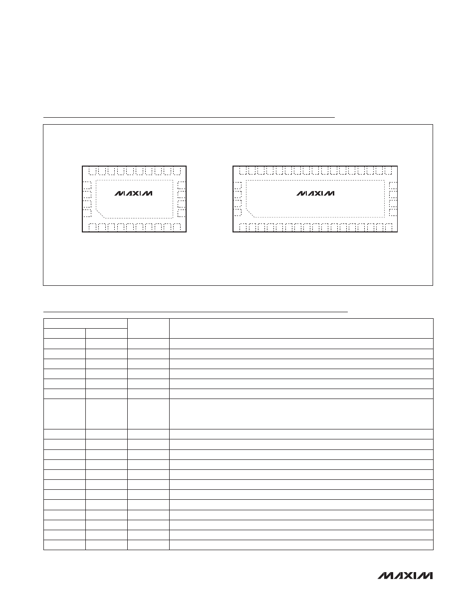
Pin Configurations
Pin Description
MAX4998
MAX14998
TOP VIEWS
TQFN
11
12
13
14
SEL2
NO3+
NO2-
NO2+
28
+
27
26
25
NC0+
NC0-
NC1+
*EP
*EP
*CONNECT EXPOSED PAD TO GROUND.
NC1-
1
2
3
4
5
6
7
8
9 10
24 23 22 21 20 19 18 17 16 15
SEL1
V
DD
COM3+
V
DD
COM2-
COM2+
COM1-
COM1+
COM0-
COM0+
V
DD
NC3+
NC2-
NC2+
V
DD
NO1-
NO1+
NO0-
NO0+
GND
TQFN
+
1
2
3
4
5
6
7
8
9 10 11 12 13 14 15 16 17
38 37 36 35 34 33 32 31 30 29 28 27 26 25 24 23 22
COM4-
V
DD
COM5+
COM5-
SEL1
SEL2
COM4+
COM3-
COM3+
COM2-
COM2+
V
DD
COM1-
COM1+
COM0-
COM0+
V
DD
18
19
20
21
NO5-
NO5+
NO4-
NO4+
42
41
40
39
NC0+
NC0-
NC1+
NC1-
NO3-
V
DD
NC4+
NC4-
NC5+
NC5-
NO3+
NO2-
NO2+
NO1-
NO1+
NO0-
NO0+
NC3-
NC3+
NC2-
NC2+
PIN
NAME
FUNCTION
MAX4998
MAX14998
1
2
COM0+
Analog Switch 1. Common positive terminal.
2
3
COM0-
Analog Switch 1. Common negative terminal.
3
4
COM1+
Analog Switch 2. Common positive terminal.
4
5
COM1-
Analog Switch 2. Common negative terminal.
5
7
COM2+
Analog Switch 3. Common positive terminal.
6
8
COM2-
Analog Switch 3. Common negative terminal.
7, 9, 15, 19
1, 6, 13, 26
VDD
Positive Supply Voltage Input. Connect VDD to a +3.0V to +3.6V supply voltage.
Bypass VDD to GND with a 0.1mF ceramic capacitor placed as close to the device as
possible (see the Board Layout section).
8
9
COM3+
Analog Switch 4. Common positive terminal.
10
16
SEL1
Control Signal Input. Selects high-frequency switching.
11
17
SEL2
Control Signal Input. Selects AUX/HPD.
12
28
NO3+
Analog Switch 4. Normally Open positive terminal.
13
29
NO2-
Analog Switch 3. Normally Open negative terminal.
14
30
NO2+
Analog Switch 3. Normally Open positive terminal.
16
36
NC3+
Analog Switch 4. Normally Closed positive terminal.
17
37
NC2-
Analog Switch 3. Normally Closed negative terminal.
18
38
NC2+
Analog Switch 3. Normally Closed positive terminal.
20
31
NO1-
Analog Switch 2. Normally Open negative terminal.
21
32
NO1+
Analog Switch 2. Normally Open positive terminal.
22
33
NO0-
Analog Switch 1. Normally Open negative terminal.