Rainbow Electronics MAX9532 User Manual
Page 9
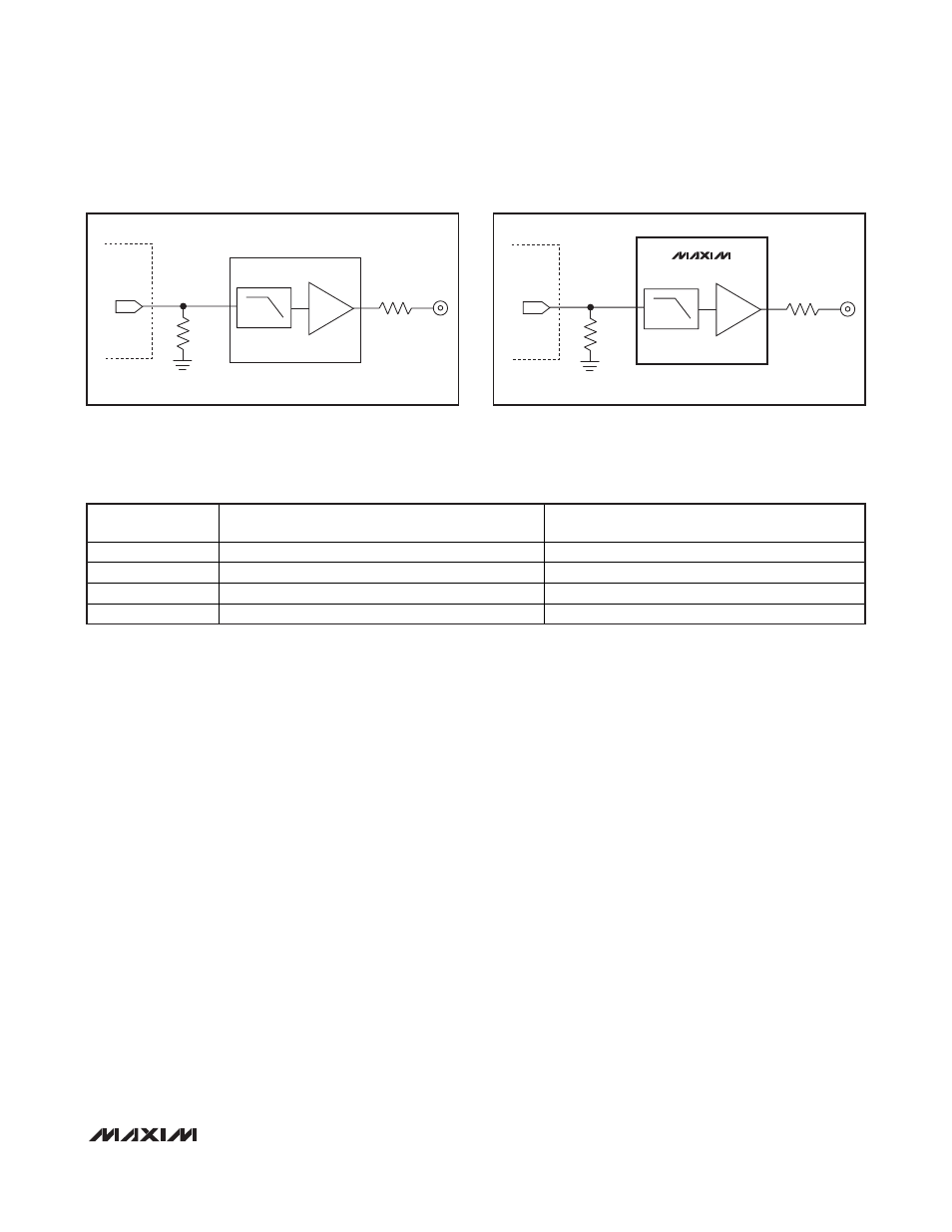
Interfacing to Video DACs that Produce
Video Signals Higher than 0.5V
P-P
Devices designed to generate 1V
P-P
video signals at
the output of the video DAC can work with the
MAX9532. Most video DACs source current into a
ground-referenced resistor, which converts the current
into a voltage. Figure 3 shows a video DAC that creates
a video signal from 0V to 1V across a 150
Ω resistor.
With a gain of 2V/V, the following video filter produces a
2V
P-P
output.
The MAX9532 accepts input signals that are 0.5V
P-P
nominally. The video DAC in Figure 3 can be made to
work with the MAX9532 by scaling down the 150
Ω
resistor to a 75
Ω resistor, as shown in Figure 4. The
75
Ω resistor is one-half the size of the 150Ω resistor,
resulting in a video signal that is one-half the amplitude.
Video Source with a Positive DC Bias
In some applications, the video source generates a sig-
nal with a positive DC voltage bias, i.e., the sync tip of
the signal is well above ground. Figure 5 shows an
example in which the outputs of the luma (Y) DAC and
the chroma (C) DAC are connected together. Since the
DACs are current-mode, the output currents sum
together into the resistor, which converts the resulting
current into a voltage representing a composite video
signal.
When the chroma DAC is connected to an independent
output resistor to ground, the chroma signal, which is a
carrier at 3.58MHz for NTSC or at 4.43MHz for PAL,
generates a positive DC bias to keep the signal above
ground at all times. When the luma DAC is connected
to an independent output resistor to ground, the luma
signal usually does not have a positive DC bias, and
the sync tip is at approximately ground. When the chro-
ma and luma signals are added together, the resulting
composite video signal generates a positive DC bias.
Therefore, the signal must be AC-coupled into the
MAX9532 because the composite video signal is above
the nominal 0V to 0.7V DC-coupled input range.
Video Signal Routing
Minimize the length of the PCB trace between the out-
put of the video DAC and the input of the MAX9532 to
reduce coupling of external noise into the video signal.
If possible, shield the PCB trace.
MAX9532
DirectDrive Video Amplifier with
Short-to-Battery Protection
_______________________________________________________________________________________
9
LPF
DAC
IMAGE
PROCESSOR
ASIC
2V/V
150
Ω
0V TO 1V
GENERIC 2V/V CONFIGURATION
2V
P-P
Figure 3. Typically, a Video DAC Generates a 1V
P-P
Signal
Across a 150
Ω Resistor Connected to Ground
LPF
2V
P-P
DAC
IMAGE
PROCESSOR
ASIC
4V/V
75
Ω
0V TO 0.5V
MAX9532
Figure 4. Video DAC Generates a 0.5V
P-P
Signal Across a 75
Ω
Resistor Connected to Ground
VIDEO SIGNAL
MAX9532 POWER CONSUMPTION (mW)
WITH 150
Ω LOAD
MAX9532 POWER CONSUMPTION (mW)
WITH 100
Ω LOAD
All Black Screen
51.236
53.978
All White Screen
57.077
65.399
75% Color Bars
53.074
57.486
50% Flat Field
49.513
51.596
Table 1. Power Consumption of the MAX9532 with Different Video Signals
Note: The supply voltage is 3.3V.