Current-limit circuit (lim) – Rainbow Electronics MAX15026 User Manual
Page 11
Current-Limit Circuit (LIM)
The current-limit circuit employs a valley and sink cur-
rent-sensing algorithm that uses the on-resistance of
the low-side MOSFET as a current-sensing element, to
eliminate costly sense resistors. The current-limit circuit
is also temperature compensated to track the on-resis-
tance variation of the MOSFET over temperature. The
current limit is adjustable with an external resistor at
LIM, and accommodates MOSFETs with a wide range
of on-resistance characteristics (see the
Setting the
Valley Current Limit
section). The adjustment range is
from 30mV to 300mV for the valley current limit, corre-
sponding to resistor values of 6k
Ω to 60kΩ. The valley
current-limit threshold across the low-side MOSFET is
precisely 1/10th of the voltage at LIM, while the sink
current-limit threshold is 1/20th of the voltage at LIM.
Valley current limit acts when the inductor current flows
towards the load, and LX is more negative than GND
during the low-side MOSFET on-time. If the magnitude
of current-sense signal exceeds the valley current-limit
threshold at the end of the low-side MOSFET on-time,
the MAX15026 does not initiate a new PWM cycle and
lets the inductor current decay in the next cycle. The
controller also rolls back the internal reference voltage
so that the controller finds a regulation point deter-
mined by the current-limit value and the resistance of
the short. In this manner, the controller acts as a con-
stant current source. This method greatly reduces
inductor ripple current during the short event, which
reduces inductor sizing restrictions, and reduces the
possibility for audible noise. After a timeout, the device
goes into hiccup mode. Once the short is removed, the
internal reference voltage soft-starts back up to the nor-
mal reference voltage and regulation continues.
MAX15026
Low-Cost, Small, 4.5V to 28V Wide Operating
Range, DC-DC Synchronous Buck Controller
______________________________________________________________________________________
11
V
CC
B
C
D
E
2048 CLK
CYCLES
2048 CLK
CYCLES
F
G
H
I
A
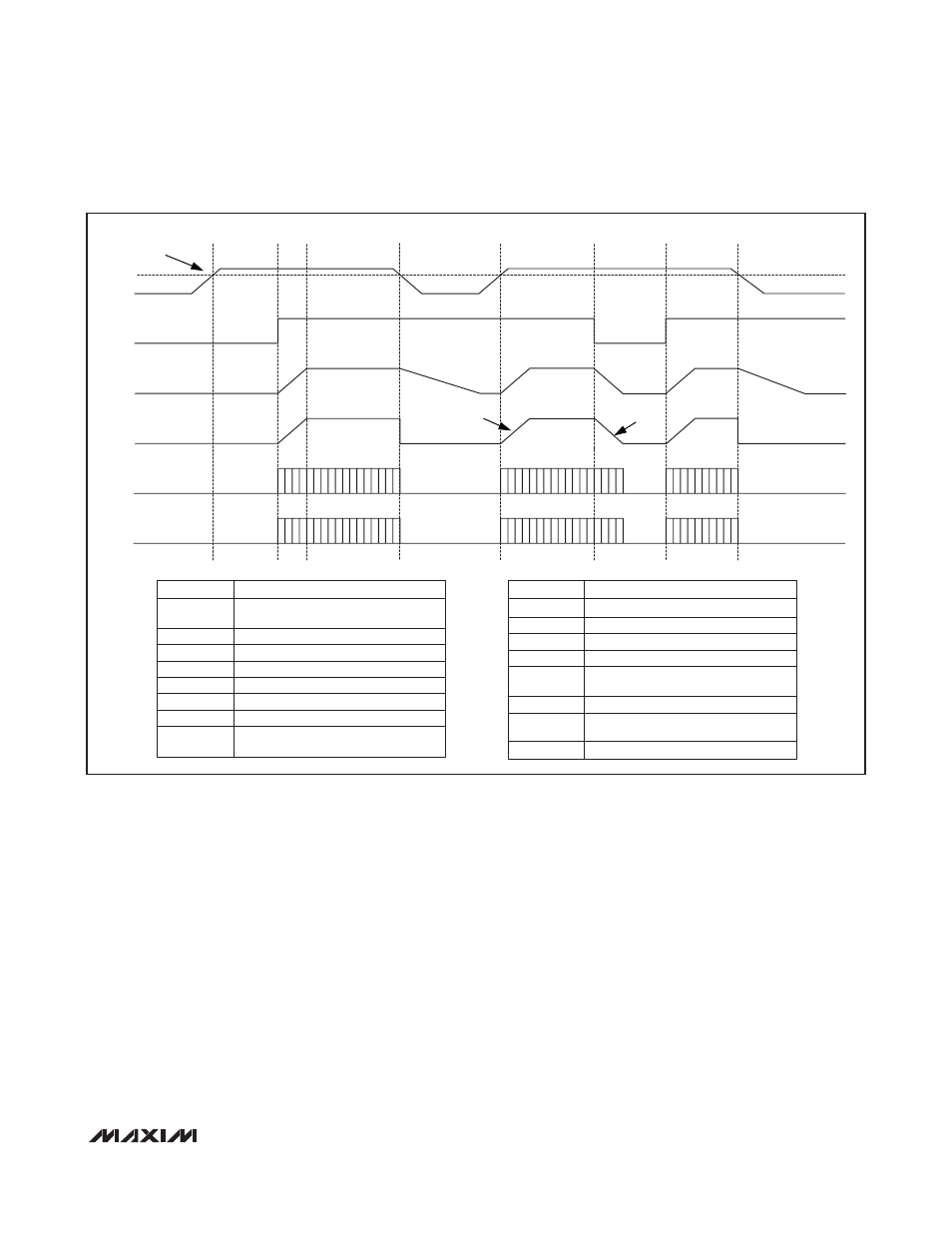
UVLO
EN
V
OUT
DAC_VREF
DH
DL
UVLO
Undervoltage threshold value is provided in
the Electrical Characteristics table.
Internal 5.25V linear regulator output.
Active-high enable input.
Regulator output voltage.
Regulator internal soft-start and soft-stop signal.
Regulator high-side gate-driver output.
Regulator low-side gate-driver output.
V
CC
rising while below the UVLO threshold.
EN is low.
V
CC
EN
V
OUT
DAC_VREF
DH
DL
A
SYMBOL
DEFINITION
B
V
CC
is higher than the UVLO threshold. EN is low.
EN is pulled high. DH and DL start switching.
Normal operation.
V
CC
drops below UVLO.
V
CC
goes above the UVLO threshold. DH and DL
start switching. Normal operation.
EN is pulled low. V
OUT
enters soft-stop.
EN is pulled high. DH and DL start switching.
Normal operation.
V
CC
drops below UVLO.
C
D
E
F
G
H
I
SYMBOL
DEFINITION
Figure 1. Power-On/-Off Sequencing