Applications information – Rainbow Electronics ADC10664 User Manual
Page 12
Applications Information
(Continued)
TL H 11192 – 13
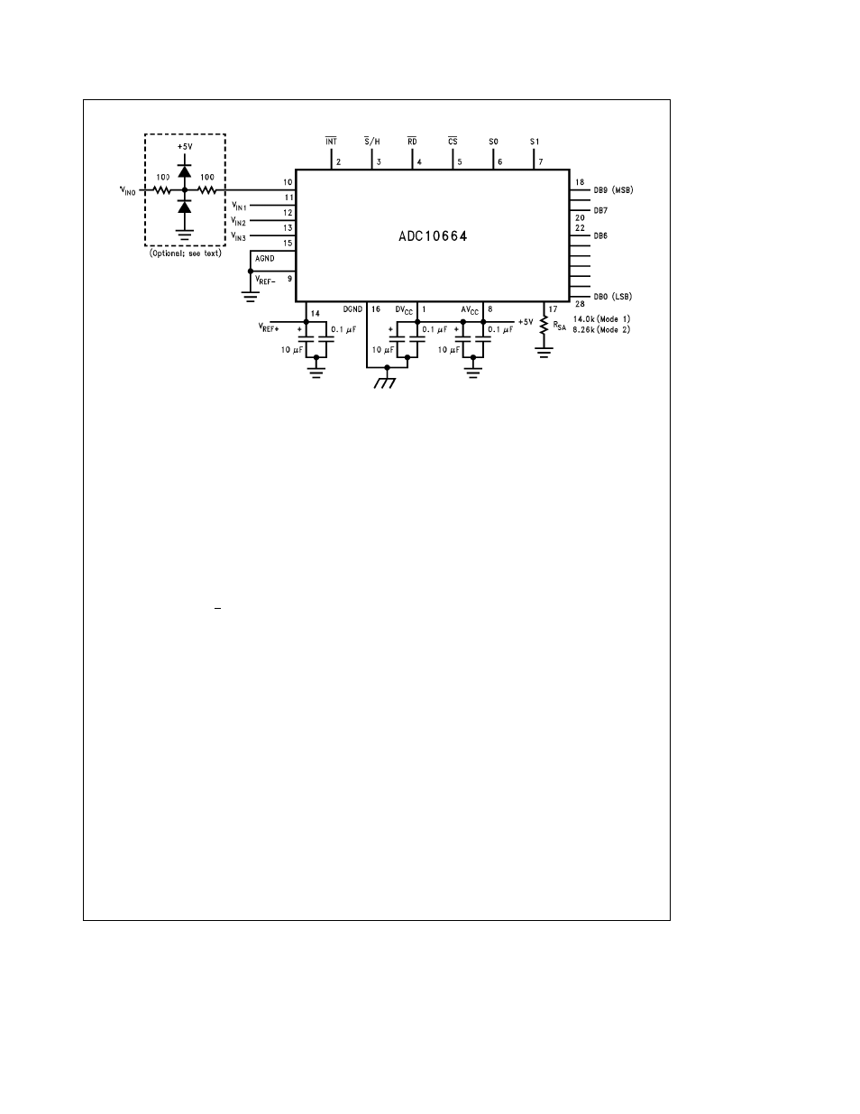
FIGURE 4 Typical Connection Note the multiple bypass capacitors on the reference and power supply pins If V
REF
b
is not grounded it should also be bypassed to analog ground using multiple capacitors (see 5 0 ‘‘Power Supply
Considerations’’) AGND and DGND should be at the same potential V
IN0
is shown with an input protection network
4 0 INHERENT SAMPLE-AND-HOLD
Because the ADC10662 and ADC10664 sample the input
signal once during each conversion they are capable of
measuring relatively fast input signals without the help of an
external sample-hold In a non-sampling successive-approx-
imation A D converter regardless of speed the input signal
must be stable to better than
g
1 2 LSB during each con-
version cycle or significant errors will result Consequently
even for many relatively slow input signals the signals must
be externally sampled and held constant during each con-
version if a SAR with no internal sample-and-hold is used
Because they incorporate a direct sample hold control in-
put the ADC10662 and ADC10664 are suitable for use in
DSP-based systems The S H input allows synchronization
of the A D converter to the DSP system’s sampling rate and
to other ADC10662s and ADC10664s
The ADC10662 and ADC10664 can perform accurate con-
versions of input signals with frequency components from
DC to over 250 kHz
5 0 POWER SUPPLY CONSIDERATIONS
The ADC10662 and ADC10664 are designed to operate
from a a5V (nominal) power supply There are two supply
pins AV
CC
and DV
CC
These pins allow separate external
bypass capacitors for the analog and digital portions of the
circuit To guarantee accurate conversions the two supply
pins should be connected to the same voltage source and
each should be bypassed with a 0 1 mF ceramic capacitor in
parallel with a 10 mF tantalum capacitor Depending on the
circuit board layout and other system considerations more
bypassing may be necessary
The ADC10662 and ADC10664 have separate analog and
digital ground pins for separate bypassing of the analog and
digital supplies Their ground pins should be connected to
the same potential and all grounds should be ‘‘clean’’ and
free of noise
In systems with multiple power supplies careful attention to
power supply sequencing may be necessary to avoid over-
driving inputs The A D converter’s power supply pins
should be at the proper voltage before digital or analog sig-
nals are applied to any of the other pins
6 0 LAYOUT AND GROUNDING
In order to ensure fast accurate conversions from the
ADC10662 and ADC10664 it is necessary to use appropri-
ate circuit board layout techniques The analog ground re-
turn path should be low-impedance and free of noise from
other parts of the system Noise from digital circuitry can be
especially troublesome so digital grounds should always be
separate from analog grounds For best performance sepa-
rate ground planes should be provided for the digital and
analog parts of the system
All bypass capacitors should be located as close to the con-
verter as possible and should connect to the converter and
to ground with short traces The analog input should be iso-
lated from noisy signal traces to avoid having spurious sig-
nals couple to the input Any external component (e g
a
filter capacitor) connected across the converter’s input
should be connected to a very clean ground return point
Grounding the component at the wrong point will result in
reduced conversion accuracy
7 0 DYNAMIC PERFORMANCE
Many applications require the A D converter to digitize AC
signals but conventional DC integral and differential nonlin-
earity specifications don’t accurately predict the A D con-
verter’s performance with AC input signals The important
specifications for AC applications reflect the converter’s
ability to digitize AC signals without significant spectral er-
rors and without adding noise to the digitized signal Dynam-
12