Nuc140 series data sheet – Rainbow Electronics NUC140 User Manual
Page 20
NUC140 Series DATA SHEET
Publication Release Date: May 31, 2010
- 20 -
Revision V1.02
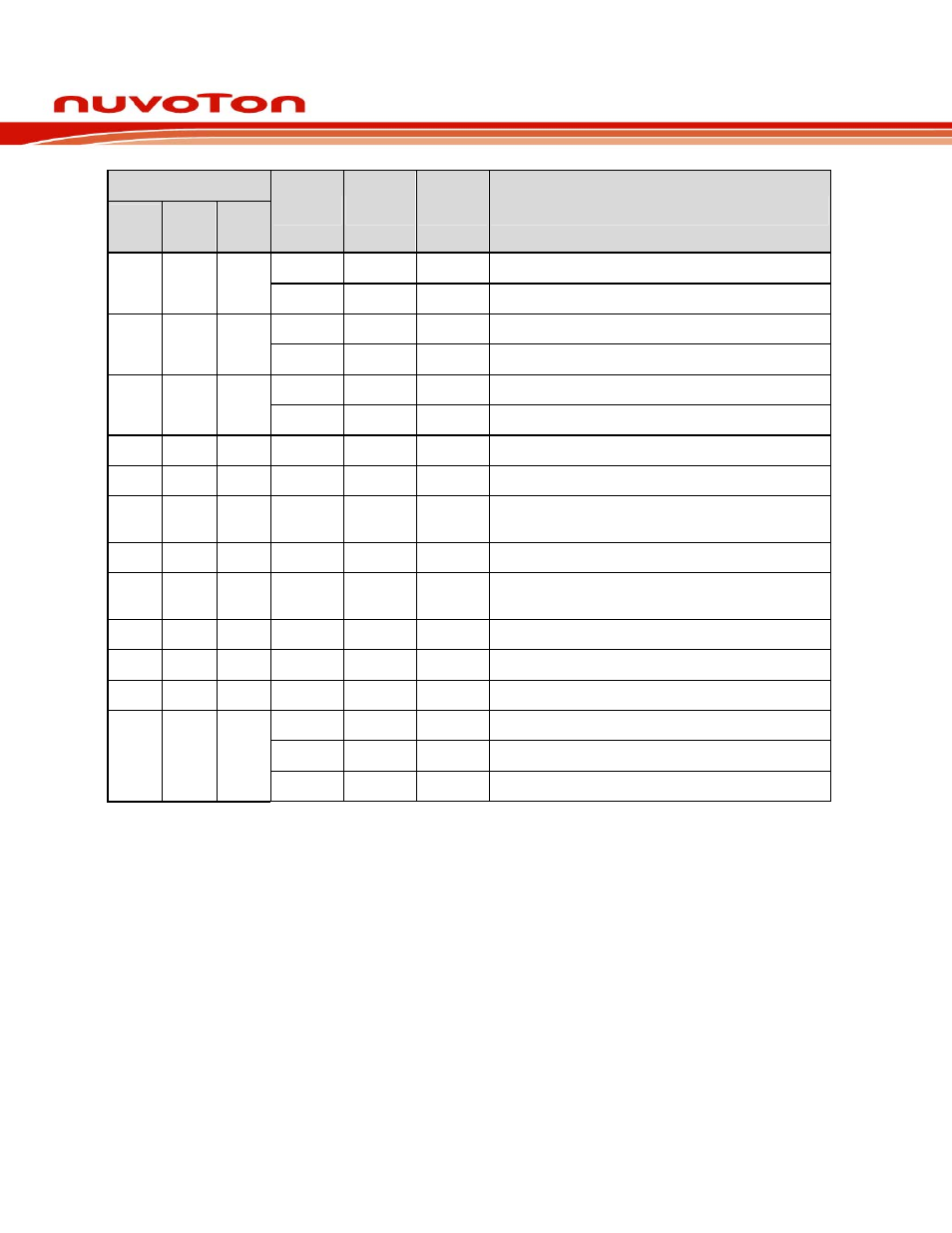
Pin No.
LQFP
100
LQFP
64
LQFP
48
Pin Name Pin Type
Description
PC.15
I/O
General purpose input/output digital pin
89 55
CPN1
I
CPN1: Comparator1 Negative input pin
PC.14
I/O
General purpose input/output digital pin
90 56
CPP1
I
CPP1: Comparator1 Positive input pin
PB.15
I/O
General purpose input/output digital pin
91 57 43
/INT1
I
/INT1: External interrupt0 input pin
92 58 44
XT1_OUT O
Crystal output pin
93 59 45
XT1_IN
I
Crystal input pin
94 60 46
/RESET I
External reset input: Low active, set this pin low reset
MCU to initial state. With internal pull-up.
95 61
VSS1
P
Ground
96 62
VDD1
P
Power supply for I/O ports and LDO source for
internal PLL and digital circuit
97
PS2DAT I/O
PS2 Data pin
98
PS2CLK I/O
PS2 clock pin
99 63 47
PVSS
I/O
PLL
Ground
PB.8
I/O
General purpose input/output digital pin
STADC
I
STADC: ADC external trigger input.
100 64 48
TM0
O
TM0: Timer0 external counter input
Note:
1.
Pin Type I=Digital Input, O=Digital Output; AI=Analog Input; P=Power Pin; AP=Analog Power