Detailed description, Pin description, Pin configuration – Rainbow Electronics MAX9920 User Manual
Page 13
Detailed Description
The MAX9918/MAX9919/MAX9920 are single-supply,
high-accuracy uni-/bidirectional current-sense amplifiers
with a high common-mode input range that extends from
-20V to +75V. The MAX9918/MAX9919/MAX9920’s input
stage utilizes a pair of level shifters allowing a wide
common-mode operating range when measuring the
voltage drop (V
SENSE
) across the current-sense resistor.
The first level shifter accommodates the upper common-
mode operating range from +2V to +75V. When the
common-mode voltage falls below +2V, the second level
shifter is used to accommodate negative voltages down
to -20V.
The level shifters translate V
SENSE
to an internal refer-
ence voltage where it is then amplified with an instru-
mentation amplifier. The instrumentation amplifier
configuration provides high precision with input offset
voltages of 400μV (max). Indirect feedback of the
instrumentation amplifier allows the gain to be adjusted
with an external resistive-divider network on the
MAX9918/MAX9920. The MAX9919 is a fixed gain
device available with laser-trimmed resistors for gains
of 45V/V (MAX9919F) and 90V/V (MAX9919N).
The MAX9918/MAX9919 operate with a full-scale sense
voltage of 50mV. The input stage of the MAX9920 pro-
vides an attenuation factor of 4, enabling a full-scale
sense voltage of 200mV.
MAX9918/MAX9919/MAX9920
-20V to +75V Input Range, Precision
Uni-/Bidirectional, Current-Sense Amplifiers
______________________________________________________________________________________
13
Pin Description
PIN
NAME
FUNCTION
1
RS+
Positive Current-Sensing Input. Power side connects to external sense resistor.
2
RS-
Negative Current-Sensing Input. Load side connects to external sense resistor.
3
SHDN
Active-High Shutdown Input. Connect to GND for normal operation.
4
GND
Ground
5
OUT
Current-Sense Output. V
OUT
is proportional to V
SENSE
.
6
FB
Feedback Input. Connect FB to a resistive-divider network to set the gain for the MAX9918 and
MAX9920. See the Adjustable Gain (MAX9918/MAX9920) section for more information. Leave FB
unconnected for the MAX9919 for proper operation.
7
REFIN
Reference Input. Set REFIN to V
CC
/2 for bidirectional operation. Set REFIN to GND for unidirectional
operation.
8
V
CC
5V Supply Voltage Input. Bypass V
CC
to GND with 0.1μF capacitor.
—
EP
Exposed Pad. Connect to a large-area contiguous ground plane for improved power dissipation. Do
not use as the only ground connection for the part.
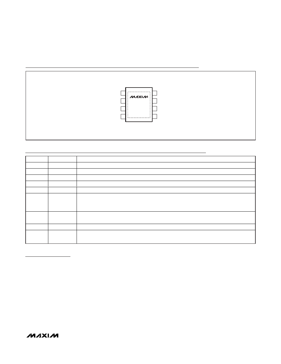
8 SOIC-EP
TOP VIEW
MAX9918
MAX9919
MAX9920
FB
OUT
8
7
V
CC
REFIN
6
5
GND
1
2
RS-
SHDN
RS+
3
4
EP*
+
*EXPOSED PAD. CONNECT EP TO SOLID GROUND FOR
PROPER THERMAL AND ELECTRICAL PERFORMANCE.
Pin Configuration