Rainbow Electronics MAX6764 User Manual
Page 14
MAX6754–MAX6764
Low-Power, Single/Dual-Voltage Window
Detectors
14
______________________________________________________________________________________
Choose R2 to have a resistance of up to 500k
Ω.
Calculate R1 by:
R1 = ((V
+
- 0.4255V) x R2) / 0.4255V
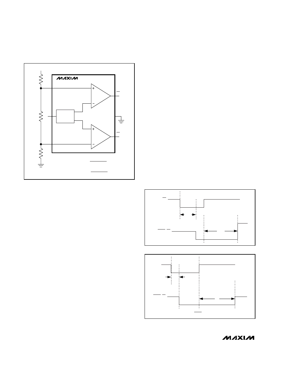
The MAX6763/MAX6764 provide inputs to a window
detector allowing the programming of the threshold
voltage to within V
CC
(see
Figure
6).
Choose R1, R2, and R3 such that:
(V+ / (R1 + R2 + R3))
≥ 1µA
SET
The MAX6754–MAX6762 allow the setting of the window
voltage range of the voltage detector. Connect SET to
GND to set a
±5% window. Connect SET to V
CC
for a
±10% window. Bias SET to V
CC
/2 for a ±15% window.
Manual Reset (
MR
)
The MAX6754–MAX6762 include an active-low manual
reset input. Drive MR low to assert a reset output
(MAX6754/MAX6755/MAX6756) or an undervoltage
output (MAX6757/MAX6758/MAX6759). The output
remains asserted for the specified propagation delay
time (see
Figure
7) after MR goes high. MR is internally
pulled to V
CC
with a 26k
Ω resistor.
Overvoltage Latch Control Input
(OVLATCH)
The MAX6760/MAX6761/MAX6762 provide an overvolt-
age latch control input (OVLATCH). Drive OVLATCH
high to latch the overvoltage output for any V
CC
or
V
CC2
overvoltage condition. Drive OVLATCH low to
clear the latch after overvoltage conditions have been
removed. The latch is transparent when OVLATCH is
connected to GND. OVLATCH is a high impedance
input. Use external pullup or pulldown.
Reset, Undervoltage, and Overvoltage
Outputs (RESET,
RESET
,
UV
, UV, OV)
RESET, RESET, UV, UV, and OV outputs assert when
the monitored supply is below the selected UV
TH
threshold or above the selected OV
TH
threshold. The
reset output deasserts after the specified timeout peri-
od when the monitored supply rises above the UV
TH
threshold or drops below the OV
TH
threshold. The
push-pull versions are referenced to V
CC
.
The MAX6760/MAX6761/MAX6762 monitor both V
CC
and V
CC2
. An under/overvoltage condition on either
voltage supply asserts the corresponding output.
RESET and UV are guaranteed to be in the correct
logic state when V
CC
or V
CC2
> 1V.
INTERNAL
REFERENCE
0.5V
GND
OV MONITOR
UV MONITOR
OV
TH
UV
TH
UV
OV
UVIN
V
CC
OVIN
MAX6763/MAX6764
V+
R1
R2
R3
OVERVOLTAGE ASSERTS WHEN
UNDERVOLTAGE ASSERTS WHEN
V+ x R3
R1 + R2 + R3
> 0.5V
< 0.5V
V+ x (R2 + R3)
R1 + R2 + R3
Figure 6. Setting the Under/Overvoltage Window
MR
RESET, UV
t
D-MR
t
MR_P
Figure 7a. Manual Reset/
Reset
Timing Diagram
t
D-UV
t
RP
V
CC
RESET, UV
(RESET IS THE COMPLEMENT OF RESET)
Figure 7b. V
CC
/RESET,
UV
Timing Diagram