Pin description (continued), Functional diagrams – Rainbow Electronics MAX6764 User Manual
Page 10
MAX6754–MAX6764
Low-Power, Single/Dual-Voltage Window
Detectors
10
______________________________________________________________________________________
Pin Description (continued)
PIN
MAX6754/
MAX6755/
MAX6756
MAX6757/
MAX6758/
MAX6759
MAX6760/
MAX6761/
MAX6762
MAX6763/
MAX6764
NAME
FUNCTION
7
—
OVLATCH
Overvoltage Output Latch Control Input. Drive OVLATCH high to latch
the overvoltage output for any V
CC
or V
CC2
overvoltage condition. Drive
OVLATCH low to clear the latch after overvoltage conditions have been
removed. The latch is transparent when OVLATCH is connected to
GND. OVLATCH is a high-impedance input. Use external pullup or
pulldown.
—
—
—
3
UVIN
Undervoltage Input. UV is low when UVIN is below the internal 0.5V
threshold. UV is high when UVIN is above the internal 0.5V threshold.
—
—
—
4
UV
Undervoltage Output. UV is low when UVIN is below the internal 0.5V
threshold. UV is high when UVIN is above the internal 0.5V threshold.
There is no timeout delay period for the UV output.
—
—
—
6
OVIN
Overvoltage Input. OV is low when OVIN is above the internal 0.5V
threshold. OV is high when OVIN is below the internal 0.5V threshold.
—
—
EP
—
EP
Exposed Pad. EP is internally connected to GND. Leave EP
unconnected or connect to GND.
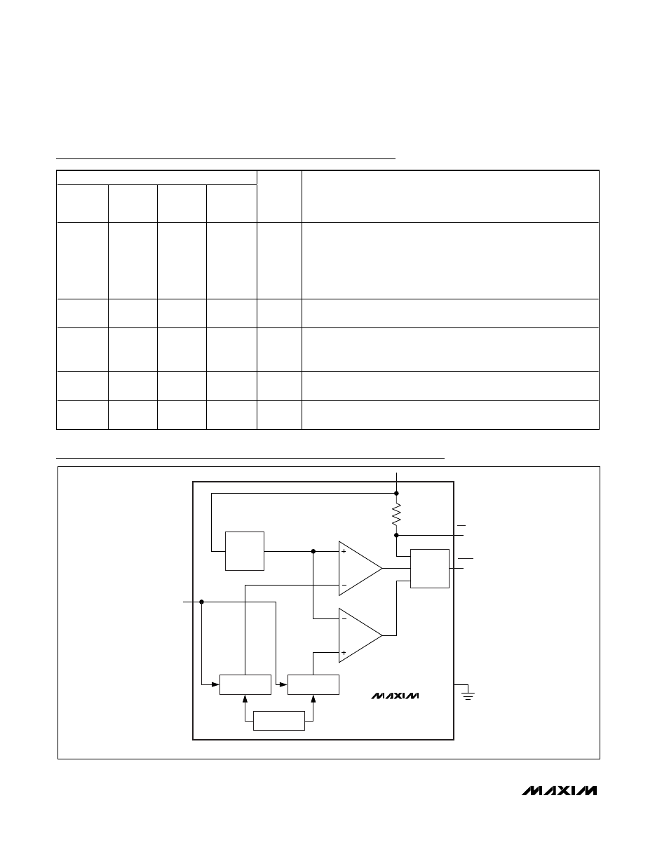
Functional Diagrams
TIMEOUT
PERIOD
OPTION
ADJUST
MONITOR
VOLTAGE
UV THRESHOLD
-5%, -10%, -15%
OV THRESHOLD
+5%, +10%, +15%
INTERNAL
REFERENCE
GND
(RESET)/
RESET
MR
V
CC
OV MONITOR
UV MONITOR
MAX6754/MAX6755/MAX6756
OV
TH
UV
TH
SET
( ) MAX6755 ONLY.
Figure 1. MAX6754/MAX6755/MAX6756 Functional Diagram