Rainbow Electronics MAX5259 User Manual
Page 13
MAX5258/MAX5259
+3V/+5V, Low-Power, 8-Bit Octal DAC
with Rail-to-Rail Output Buffers
______________________________________________________________________________________
13
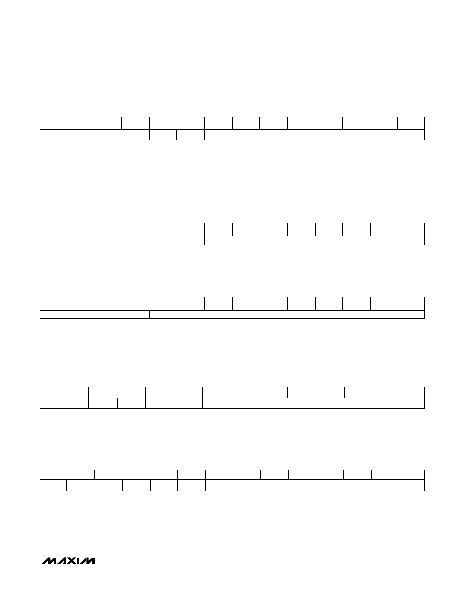
The clear command clears all input and DAC registers and sets all DAC outputs to zero. This command brings the
DAC out of shutdown.
Shuts down all output buffer amplifiers and voltage references. Output buffers can be individually disabled with the cor-
responding zeros in the data bits (D7-D0). If all data bits are zero, only the power-on reset circuit is active, and the
device draws 10µA (max). There are four ways to bring the device out of shutdown: POR, CLEAR, LOAD SAME DATA,
LOAD INPUT, AND DAC REGISTERS.
This command sets DOUT to transition at the falling edge of SCLK. The same command also updates all DAC regis-
ters with the contents of their respective input registers, identical to the LDAC command. This is the default mode on
power-up.
A2
A1
A0
C2
C1
C0
D7
D6
D5
D4
D3
D2
D1
D0
Don’t Care
0
0
1
Don’t Care
Clear
(LDAC = X)
A2
A1
A0
C2
C1
C0
D7
D6
D5
D4
D3
D2
D1
D0
Don’t Care
0
1
0
8-Bit Data
Software Shutdown
(LDAC = X)
A2
A1
A0
C2
C1
C0
D7
D6
D5
D4
D3
D2
D1
D0
0
X
X
0
1
1
8-Bit Data
Set DOUT Phase—SCLK Falling (Mode 0, Default)
(LDAC = X)
A2
A1
A0
C2
C1
C0
D7
D6
D5
D4
D3
D2
D1
D0
1
X
X
0
1
1
8-Bit Data
Set DOUT Phase—SCLK Rising (Mode 1)
(LDAC = X)
A2
A1
A0
C2
C1
C0
D7
D6
D5
D4
D3
D2
D1
D0
Don’t Care
0
0
0
Don’t Care
No Operation (NOP)
(LDAC = X)
The no-operation (NOP) command allows data to be shifted through the MAX5258/MAX5259 shift register without
affecting the input or DAC registers. This is useful in daisy-chaining (see the Daisy-Chaining Devices section). For
this command, the data bits are "Don’t Cares." As an example, three MAX5258s are daisy-chained (A, B, and C), and
devices A and C need to be updated. The 48-bit-wide command would consist of one 16-bit word for device C, fol-
lowed by an NOP instruction for device B and a third 16-bit word with data for device A. At the rising edge of CS,
device B will not change state.
Mode 1 sets the serial output DOUT to transition at the rising edge of SCLK. Once this command is issued, DOUT’s
phase is latched and will not change except on power-up or if the specific command to set the phase to falling edge
is issued.
This command also loads all DAC registers with the contents of their respective input registers, and is identical to the
LDAC command.