Electrical characteristics (continued) – Rainbow Electronics MAX8758 User Manual
Page 5
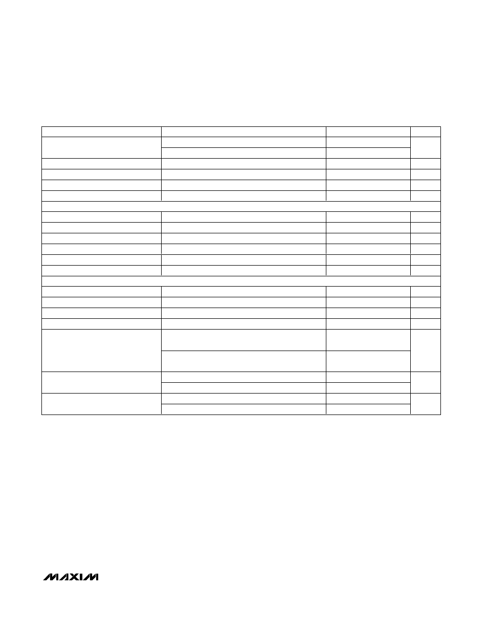
PARAMETER
CONDITIONS
MIN
TYP
MAX
UNITS
FREQ = GND
91
99
Oscillator Maximum Duty Cycle
FREQ = IN
88
96
%
FB Regulation Voltage
1.220
1.252
V
FB Transconductance
∆I = 5µA at COMP
75
280
µS
LX On-Resistance
I
LX
= 200mA
200
m
Ω
LX Current Limit
65% duty cycle
2.0
3.0
A
POSITIVE GATE DRIVER TIMING AND CONTROL SWITCHES
SRC Input Voltage Range
28
V
SRC Input Current
MODE
= DLP = CTL = LDO
250
µA
DRN Input Current
MODE = DLP = LDO, V
DRN
= 8V, V
CTL
= 0
250
µA
SRC-to-GON Switch On-Resistance
DLP = CTL = LDO
30
Ω
DRN-to-GON Switch On-Resistance
DLP = LDO, V
CTL
= 0
130
Ω
THR-to-GON Voltage Gain
V
GON
= 12V, V
THR
= 1.2V
9.7
10.3
V/V
OPERATIONAL AMPLIFIER
SUPB Supply Range
4.5
13.0
V
SUPB Supply Current
Buffer configuration, V
POSB
= 4V, no load
1.0
mA
Input Offset Voltage
V
NEGB
, V
POSB
= V
SUPB
/ 2
18
mV
Input Common-Mode Voltage Range
0
V
SUPB
V
I
OUTB
= 100µA
V
SUPB
- 15
Output Voltage Swing High
I
OUTB
= 5mA
V
SUPB
- 150
mV
I
OUTB
= -100µA
15
Output Voltage Swing Low
I
OUTB
= -5mA
150
mV
OUTB shorted to V
SUPB
/2, sourcing
75
Short-Circuit Current
OUTB shorted to V
SUPB
/2, sinking
75
mA
MAX8758
Step-Up Regulator with Switch Control and
Operational Amplifier for TFT LCD
_______________________________________________________________________________________
5
ELECTRICAL CHARACTERISTICS (continued)
(V
IN
= V
SHDN
= +3V, OUT = +10V, FREQ = GND,
T
A
= -40°C to +85°C, unless otherwise noted.) (Note 2)
Note 1: OUT and SUP can operate down to 4.5V. LDO will be out of regulation, but IC will function correctly.
Note 2: -40°C specs are guaranteed by design, not production tested.