Max8758, Table 2. component suppliers – Rainbow Electronics MAX8758 User Manual
Page 12
MAX8758
The internal n-channel power MOSFET reduces the
number of external components. The supply rail of the
internal gate driver is bootstrapped to the internal linear
regulator output to improve the efficiency at low-input
voltages. The external-capacitor, soft-start function
effectively controls inrush currents. The output voltage
can be set from V
IN
to 13V with an external resistive
voltage-divider.
PWM Control Block
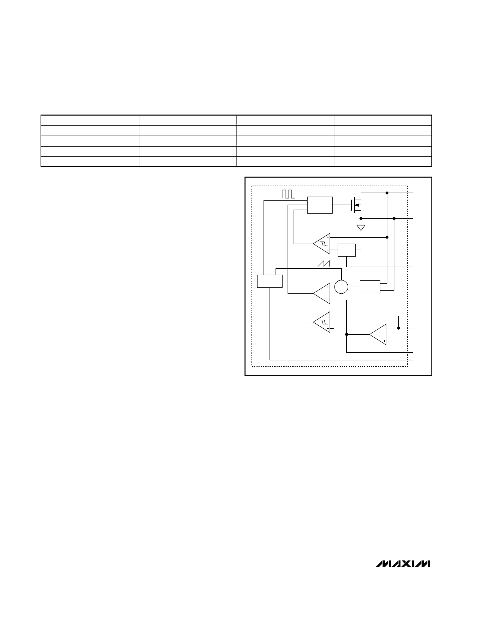
Figure
3 is the block diagram of the step-up regulator.
The regulator controls the output voltage and the power
delivered to the output by modulating the duty cycle (D)
of the internal power MOSFET in each switching cycle.
The duty cycle of the MOSFET is approximated by:
where V
OUT
is the output voltage of the step-up regulator.
On the rising edge of the internal oscillator clock, the
controller sets a flip-flop, turning on the n-channel
MOSFET and applying the input voltage across the
inductor. The current through the inductor ramps up lin-
early, storing energy in its magnetic field. A transcon-
ductance error amplifier compares the FB voltage with
a 1.24V (typ) reference voltage. The error amplifier
changes the COMP voltage by charging or discharging
the COMP capacitor. The COMP voltage is compared
with a ramp, which is the sum of the current-sense sig-
nal and a slope compensation signal. Once the ramp
signal exceeds the COMP voltage, the controller resets
the flip-flop and turns off the MOSFET. Since the induc-
tor current is continuous, a transverse potential devel-
ops across the inductor that turns on the Schottky
diode (D1 in
Figure
1). The voltage across the inductor
then becomes the difference between the output volt-
age and the input voltage. This discharge condition
forces the current through the inductor to ramp down,
transferring the energy stored in the magnetic field to
the output capacitor and the load. The MOSFET
remains off for the rest of the clock cycle.
Bootstrapping and Soft-Start
The MAX8758 features bootstrapping operation. In nor-
mal operation, the internal linear regulator supplies
power to the internal circuitry. The input of the linear
regulator (OUT) should be directly connected to the
output of the step-up regulator. The step-up regulator is
enabled when the input voltage at OUT is above 1.75V,
SHDN is high, and the fault latch is not set.
After being enabled, the regulator starts open-loop
switching to generate the supply voltage for the linear
regulator with a controlled duty cycle. The internal ref-
erence block turns on when the LDO voltage exceeds
2.7V (typ). When the reference voltage reaches regula-
tion, the PWM controller and the current-limit circuit are
enabled and the step-up regulator enters soft-start.
D
V
V
V
OUT
IN
OUT
≈
−
Step-Up Regulator with Switch Control and
Operational Amplifier for TFT LCD
12
______________________________________________________________________________________
Table 2. Component Suppliers
SUPPLIER
PHONE
FAX
WEBSITE
Fairchild Semiconductor
408-822-2000
408-822-2102
www.fairchildsemi.com
Sumida
847-545-6700
847-545-6720
www.sumida.com
TDK
847-803-6100
847-390-4405
www.component.tdk.com
Toshiba
949-455-2000
949-859-3963
www.toshiba.com/taec
∑
SOFT-
START
CURRENT
SENSE
OSCILLATOR
LOGIC AND
DRIVER
CLOCK
SLOPE COMP
TO FAULT LOGIC
1.0V
1.24V
I
LIMIT
LX
PGND
SS
FB
COMP
FREQ
ILIM
COMPARATOR
PWM
COMPARATOR
FAULT
COMPARATOR
ERROR AMP
Figure 3. Step-Up Regulator Block Diagram