Detailed description, Internal nfet switch – Rainbow Electronics MAX4987BE User Manual
Page 6
MAX4987AE/MAX4987BE
Detailed Description
The MAX4987AE/MAX4987BE are overvoltage protec-
tion devices with integrated ESD protection for USB
data lines. These devices feature a low R
ON
internal
FET and protect low-voltage systems against voltage
faults up to +28V. If the input voltage exceeds the over-
voltage threshold, the internal nFET switch is turned off
to prevent damage to the protected components. The
30ms debounce time prevents false turn-on of the inter-
nal nFET switch during startup. An open-drain active-
low logic output is available to signal that a successful
power-up has occurred.
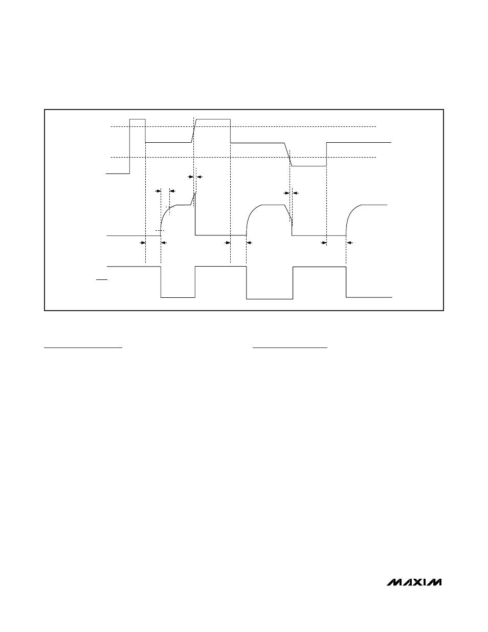
Device Operation
The MAX4987AE/MAX4987BE have an internal oscilla-
tor and charge pump that control the turn-on of the
internal nFET switch. The internal oscillator controls the
timers that enable the turn-on of the charge pump and
controls the state of the open-drain
ACOK output. If V
IN
< V
UVLO
or if V
IN
> V
OVLO
, the internal oscillator
remains off, thus disabling the charge pump. If V
UVLO
<
V
IN
< V
OVLO
, the internal charge pump is enabled. The
charge-pump startup, after a 30ms internal delay, turns
on the internal nFET switch and asserts
ACOK (see
Figure 1). At any time, if V
IN
drops below V
UVLO
or rises
above V
OVLO
,
ACOK is pulled high and the charge
pump is disabled.
Internal nFET Switch
The MAX4987AE/MAX4987BE incorporate an internal
nFET switch with a 100mΩ (typ) on-resistance. The
nFET switch is internally driven by a charge pump that
generates a voltage above the input voltage. The
MAX4987AE/MAX4987BE is equipped with a 1.5A (min)
current-limit protection that turns off the nFET switch
within 5µs (typ) during an overcurrent fault condition.
Autoretry
The MAX4987AE/MAX4987BE have an overcurrent
autoretry function that turns on the nFET switch again
after a 30ms (typ) retry time (see Figure 2). If the faulty
load condition is still present after the blanking time, the
switch turns off again and the cycle is repeated. The fast
turn-off time and 30ms retry time result in a very low duty
cycle in order to keep power consumption low. If the
faulty load condition is not present, the switch remains on.
Undervoltage Lockout (UVLO)
The MAX4987AE has a 2.55V undervoltage-lockout
threshold (UVLO), while the MAX4987BE has a 4.15V
UVLO threshold. When V
IN
is less than V
UVLO
,
ACOK is
high impedance.
Overvoltage-Protection Controller
with USB ESD Protection
6
_______________________________________________________________________________________
UVLO
OVLO
t
INDBC
t
ON
IN
OUT
ACOK
t
INDBC
t
OFF
90% V
OUT
t
INDBC
t
OFF
10% V
OUT
Figure 1. MAX4987AE/MAX4987BE Timing Diagram