Pin description – Rainbow Electronics MAX8815A User Manual
Page 7
MAX8815A
1A, 97% Efficiency, 30µA Quiescent Current
Step-Up Converter with True Shutdown
_______________________________________________________________________________________
7
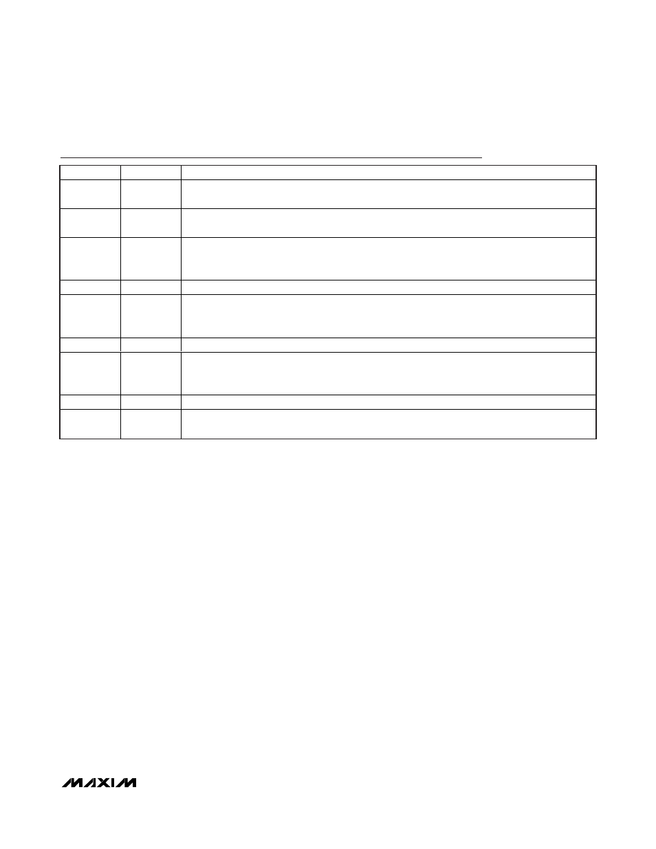
Pin Description
PIN
NAME
FUNCTION
1, 2
LX
Inductor Connection. LX pins are internally connected. Connect the LX pins to the switched side of
the inductor. LX is high impedance in shutdown.
3
BATT
Supply Voltage Input. Connect BATT to an input supply between 1.2V and 5V. Bypass BATT to EP
with two 4.7µF ceramic capacitors or one 10µF ceramic capacitor.
4
ON
Logic On/Off Input. Drive ON low to place the MAX8815A into shutdown. During shutdown, the
control circuitry, internal switching MOSFET, and synchronous rectifier turn off and LX becomes high
impedance. Drive ON high for normal operation.
5
GND
Analog Ground
6
FB
Feedback Input. Connect FB to POUT to set V
OUT
= 5V. For other output voltages, connect a resistor-
divider from POUT to GND (see the Setting the Output Voltage section). FB regulates to 1.265V (typ)
and is high impedance in shutdown.
7
OUTS
Power Bootstrapped Input. Connect OUTS to POUT through an RC filter.
8
SKIPB
PWM Mode Selection Input. Drive SKIPB low to select the normal mode of operation. Normal mode is
fixed PWM at medium to heavy loads and skip mode at light loads. Drive SKIPB high to select the
forced-PWM mode of operation.
9, 10
POUT
Converter Output. Bypass POUT to EP with one 22µF tantalum capacitor.
—
EP
Exposed Paddle. Connect to the ground plane to optimize thermal performance. EP is internally
connected to GND. EP must be connected to GND at a single point with a star ground connection.