Electrical characteristics (continued) – Rainbow Electronics MAX8815A User Manual
Page 3
MAX8815A
1A, 97% Efficiency, 30µA Quiescent Current
Step-Up Converter with True Shutdown
_______________________________________________________________________________________
3
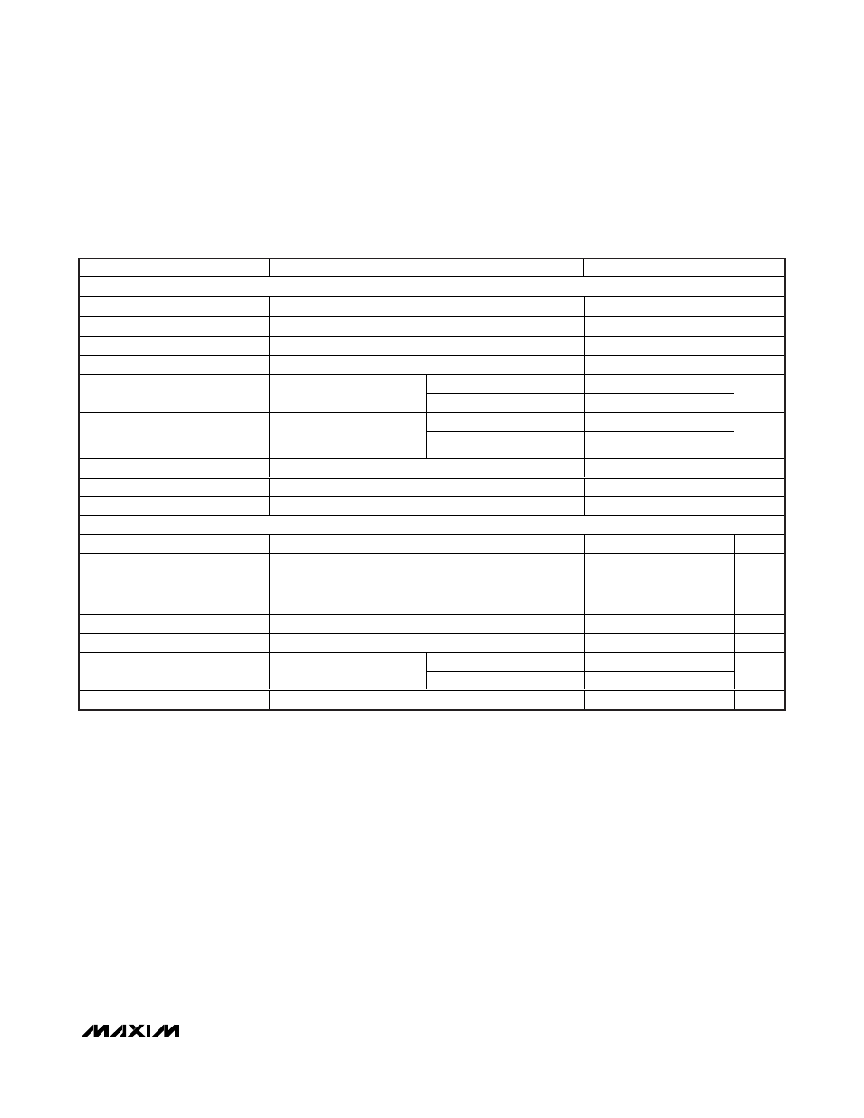
PARAMETER
CONDITIONS
MIN
TYP
MAX
UNITS
DC-DC SWITCHES
p-Channel On-Resistance
0.14
0.25
Ω
n-Channel On-Resistance
0.1
0.17
Ω
n-Channel Current Limit
2.20
2.5
2.75
A
p-Channel Turn-Off Current
10
mA
T
A
= +25°C
0.1
2
OUT Leakage Current
V
LX
= V
ON
= 0V, V
OUTS
=
V
POUT
= V
BATT
= 5.5V
T
A
= +85°C
0.2
µA
T
A
= +25°C
0.1
2
LX Leakage Current
V
LX
= 0V or 5.5V, V
OUTS
=
V
POUT
= V
BATT
= 5.5V,
V
ON
= 0V
T
A
= +85°C
0.2
µA
Soft-Start Interval
Load dependent
6
ms
Overload Protection Fault Delay
16
ms
Startup into a Short Circuit
6
ms
LOGIC INPUTS
ON Input Low Level
V
OUTS
= V
POUT
= 0V and 1.5V < V
BATT
< 5.5V
0.5
V
ON Input High Level
V
OUTS
= V
POUT
= 0V and 1.5V < V
BATT
< 5.5V, V
H
is the
highter of V
POUT
and V
BATT
V
H
-
0.2V
(1.3V
max)
V
SKIPB Input Low Level
3.3V < V
POUT
< V
OUT
< 5.5V
0.5
V
SKIPB Input High Level
3.3V < V
POUT
< V
OUT
< 5.5V
1.6
V
T
A
= +25°C
0.01
1
ON, SKIPB Input Leakage
Current
V
OUTS
= V
POUT
= V
BATT
=
5.5V
T
A
= +85°C
0.02
µA
Thermal Shutdown
+167
°C
ELECTRICAL CHARACTERISTICS (continued)
(V
OUTS
= V
POUT
= 5V, V
ON
= V
BATT
= 3.6V, V
SKIPB
= GND, T
A
= -40°C to +85°C, typical values are at T
A
= +25°C, unless otherwise
noted. Limits are 100% production tested at T
A
= +25°C. Limits over the operating temperature range are guaranteed by design and
characterization.)
Note 3: Guaranteed by design. Not production tested.
Note 4: The idle-mode current threshold is the transition point between fixed-frequency PWM operation and idle-mode operation. The
specification is given in terms of output load current for inductor values shown in the typical application circuits (Figure 1). The
idle-mode transition varies with input-to-output voltage ratio.