Detailed description, Pin description – Rainbow Electronics MAX9700 User Manual
Page 8
MAX9700
1.2W, Low-EMI, Filterless,
Class D Audio Amplifier
8
_______________________________________________________________________________________
Detailed Description
The MAX9700 filterless, class D audio power amplifier
features several improvements to switch-mode amplifier
technology. The MAX9700 offers class AB performance
with class D efficiency, while occupying minimal board
space. A unique filterless modulation scheme, synchro-
nizable switching frequency, and SSM mode create a
compact, flexible, low-noise, efficient audio power
amplifier. The differential input architecture reduces
common-mode noise pickup, and can be used without
input-coupling capacitors. The device can also be con-
figured as a single-ended input amplifier.
Comparators monitor the MAX9700 inputs and com-
pare the complementary input voltages to the sawtooth
waveform. The comparators trip when the input magni-
tude of the sawtooth exceeds their corresponding input
voltage. Both comparators reset at a fixed time after the
rising edge of the second comparator trip point, gener-
ating a minimum-width pulse t
ON(MIN)
at the output of
the second comparator (Figure 1). As the input voltage
increases or decreases, the duration of the pulse at one
output increases (the first comparator to trip) while the
other output pulse duration remains at t
ON(MIN)
. This
causes the net voltage across the speaker (V
OUT+
-
V
OUT-
) to change.
Operating Modes
Fixed-Frequency Modulation (FFM) Mode
The MAX9700 features two FFM modes. The FFM
modes are selected by setting SYNC = GND for a
1.1MHz switching frequency, and SYNC = FLOAT for a
1.45MHz switching frequency. In FFM mode, the fre-
quency spectrum of the class D output consists of the
fundamental switching frequency and its associated
harmonics (see the Wideband FFT graph in the Typical
Operating Characteristics). The MAX9700 allows the
switching frequency to be changed by +32%, should
the frequency of one or more of the harmonics fall in a
sensitive band. This can be done at any time and does
not affect audio reproduction.
Spread-Spectrum Modulation (SSM) Mode
The MAX9700 features a unique, patented spread-spec-
trum mode that flattens the wideband spectral compo-
nents, improving EMI emissions that may be radiated by
the speaker and cables by 5dB. Proprietary techniques
ensure that the cycle-to-cycle variation of the switching
period does not degrade audio reproduction or efficien-
cy (see the Typical Operating Characteristics). Select
SSM mode by setting SYNC = V
DD
. In SSM mode, the
switching frequency varies randomly by
±120kHz
around the center frequency (1.22MHz). The modulation
scheme remains the same, but the period of the saw-
tooth waveform changes from cycle to cycle (Figure 2).
Instead of a large amount of spectral energy present at
multiples of the switching frequency, the energy is now
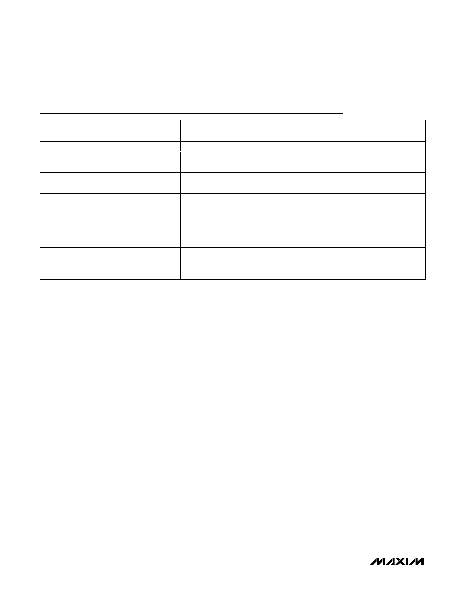
Pin Description
PIN
BUMP
TDFN/µMAX
UCSP
NAME
FUNCTION
1
C4
V
DD
Analog Power Supply
2
B4
IN+
Noninverting Audio Input
3
A4
IN-
Inverting Audio Input
4
A3
GND
Analog Ground
5
B3
SHDN
Active-Low Shutdown Input. Connect to V
DD
for normal operation.
6
C2
SYNC
Frequency Select and External Clock Input.
SYNC = GND: Fixed-frequency mode with f
S
= 1100kHz.
SYNC = Float: Fixed-frequency mode with f
S
= 1450kHz.
SYNC = V
DD
: Spread-spectrum mode with f
S
= 1220kHz
±120kHz.
SYNC = Clocked: Fixed-frequency mode with f
S
= external clock frequency.
7
B2
PGND
Power Ground
8
C1
OUT+
Amplifier Output Positive Phase
9
A1
OUT-
Amplifier Output Negative Phase
10
B1
PV
DD
H-Bridge Power Supply