Stereo configuration, Designing with volume control – Rainbow Electronics MAX9700 User Manual
Page 13
MAX9700
1.2W, Low-EMI, Filterless,
Class D Audio Amplifier
______________________________________________________________________________________
13
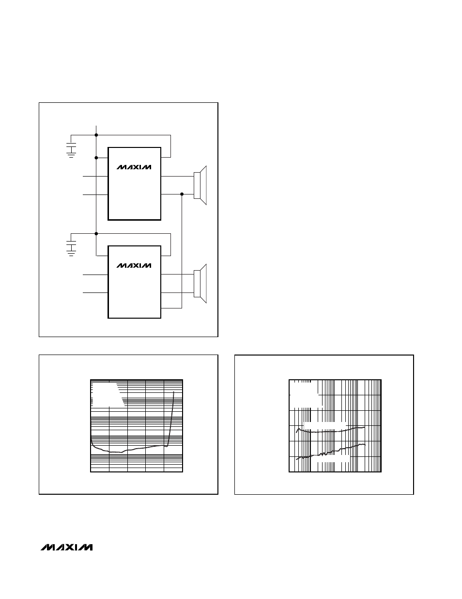
Stereo Configuration
Two MAX9700s can be configured as a stereo amplifier
(Figure 7). Device U1 is the master amplifier; its unfil-
tered output drives the SYNC input of the slave device
(U2), synchronizing the switching frequencies of the two
devices. Synchronizing two MAX9700s ensures that no
beat frequencies occur within the audio spectrum. This
configuration works when the master device is in either
FFM or SSM mode. There is excellent THD+N perfor-
mance and minimal crosstalk between devices due to
the SYNC connection (Figures 8 and 9). U2 locks onto
only the frequency present at SYNC, not the pulse
width. The internal feedback loop of device U2 ensures
that the audio component of U1’s output is rejected.
Designing with Volume Control
The MAX9700 can easily be driven by single-ended
sources (Figure 6), but extra care is needed if the
source impedance “seen” by each differential input is
unbalanced, such as the case in Figure 10a, where the
MAX9700 is used with an audio taper potentiometer
acting as a volume control. Functionally, this configura-
tion works well, but can suffer from click-pop transients
at power-up (or coming out of SHDN) depending on the
volume-control setting. As shown, the click-pop perfor-
mance is fine for either max or min volume, but worsens
at other settings.
Figure 7. Master-Slave Stereo Configuration
IN+
IN-
OUT+
OUT-
SYNC
1
µF
RIGHT-CHANNEL
DIFFERENTIAL
AUDIO INPUT
MAX9700
V
DD
V
DD
PV
DD
IN+
IN-
OUT+
OUT-
SYNC
1
µF
LEFT-CHANNEL
DIFFERENTIAL
AUDIO INPUT
MAX9700
V
DD
PV
DD
Figure 8. Master-Slave THD+N
100
0
0.1
0.2
0.3
0.4
0.5
10
1
0.1
0.01
0.001
TOTAL HARMONIC DISTORTION PLUS NOISE
vs. OUTPUT POWER
OUTPUT POWER (W)
THD+N (%)
V
DD
= 3.3V
f = 1kHz
R
L
= 8
Ω
SLAVE DEVICE
0
-120
-100
10
100
1k
10k
100k
CROSSTALK vs. FREQUENCY
-80
FREQUENCY (Hz)
CROSSTALK (dB)
-60
-40
-20
MASTER-TO-SLAVE
SLAVE-TO-MASTER
V
DD
= 3.3V
R
L
= 8
Ω
f = 1kHz
V
IN
= 500mV
P-P
Figure 9. Master-Slave Crosstalk