Pin description – Rainbow Electronics MAX9508 User Manual
Page 9
MAX9508
Video Filter Amplifier with SmartSleep and
Bidirectional Video Support
_______________________________________________________________________________________
9
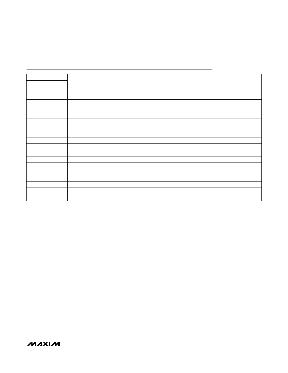
Pin Description
PIN
TQFN
QSOP
NAME
FUNCTION
1, 13
3, 15
V
DD
Power Supply. Bypass V
DD
with a 0.1µF capacitor to ground.
2
4
YIN
Luma Video Input. Directly connect this input to the video DAC output.
3, 8
5, 10
GND
Ground
4
6
CVBSIN
Internal CVBS Signal Input. Directly connect this input to the video DAC output.
5
7
EXTCVBSIN
External CVBS Signal Input. AC-couple the signal through a 0.1µF capacitor to this input.
6
8
SHDN
Active-Low Shutdown Logic Input. Connect to logic low to place device in shutdown.
Connect to logic high for normal operation.
7
9
N.C.
No Connection. Connect to GND.
9
11
CVBSOUT2
CVBS Output 2
10
12
CVBSOUT1
CVBS Output 1. CVBSOUT1 is actively pulled to GND when INT/EXT is logic high.
11
13
YOUT
Luma Video Output
12
14
COUT
Chroma Video Output
14
16
INT/EXT
Internal/External CVBS Logic Input. Connect INT/EXT low to process CVBS video signals
from CVBSIN input. Connect INT/EXT high to process CVBS video signals from EXTCVBSIN
input.
15
1
SMARTSLEEP
SmartSleep Logic Input. Connect to logic high to activate SmartSleep operation.
16
2
CIN
Chroma Video Input. Directly connect this input to the video DAC output.
EP
—
EP
Exposed Pad. Connect EP to GND. EP is also internally connected to GND.