Wired remote controllers – Rainbow Electronics MAX11042 User Manual
Page 10
MAX11041/MAX11042
4) The MAX11041/MAX11042 send the latest keypress
type (K7–K0) stored in the FIFO starting with the
most-significant bit. Afterwards the master must
send an ACK bit.
5) The MAX11041/MAX11042 send the corresponding
keypress time duration (OF, T6–T0) stored in the
FIFO starting with the most significant bit (OF).
Afterwards the master must send an ACK bit.
6) The master must generate a stop condition (P).
Slave Address and R/W Bit
The MAX11041/MAX11042 include a 7-bit slave
address. The first 5 bits (MSBs) of the slave address
are factory-programmed and always 01000. The logic
state of the address inputs (A1 and A0) determine the
last two LSBs of the device address (see
Figure 6).
Connect A1 and A0 to V
DD
(logic high) or GND (logic
low). A maximum of four MAX11041/MAX11042 devices
can be connected on the same bus at one time using
these address inputs. The 8th bit of the address byte is
a read/write bit (R/W). If this bit is set to 0, the device
expects to receive data. If this bit is set to 1, the device
expects to send data.
Wired Remote Controllers
10
______________________________________________________________________________________
1
2
3
4
5
6
7
8
9
0
1
0
0
0
A1
A2
SDA
SCL
ACK
S
R/
W
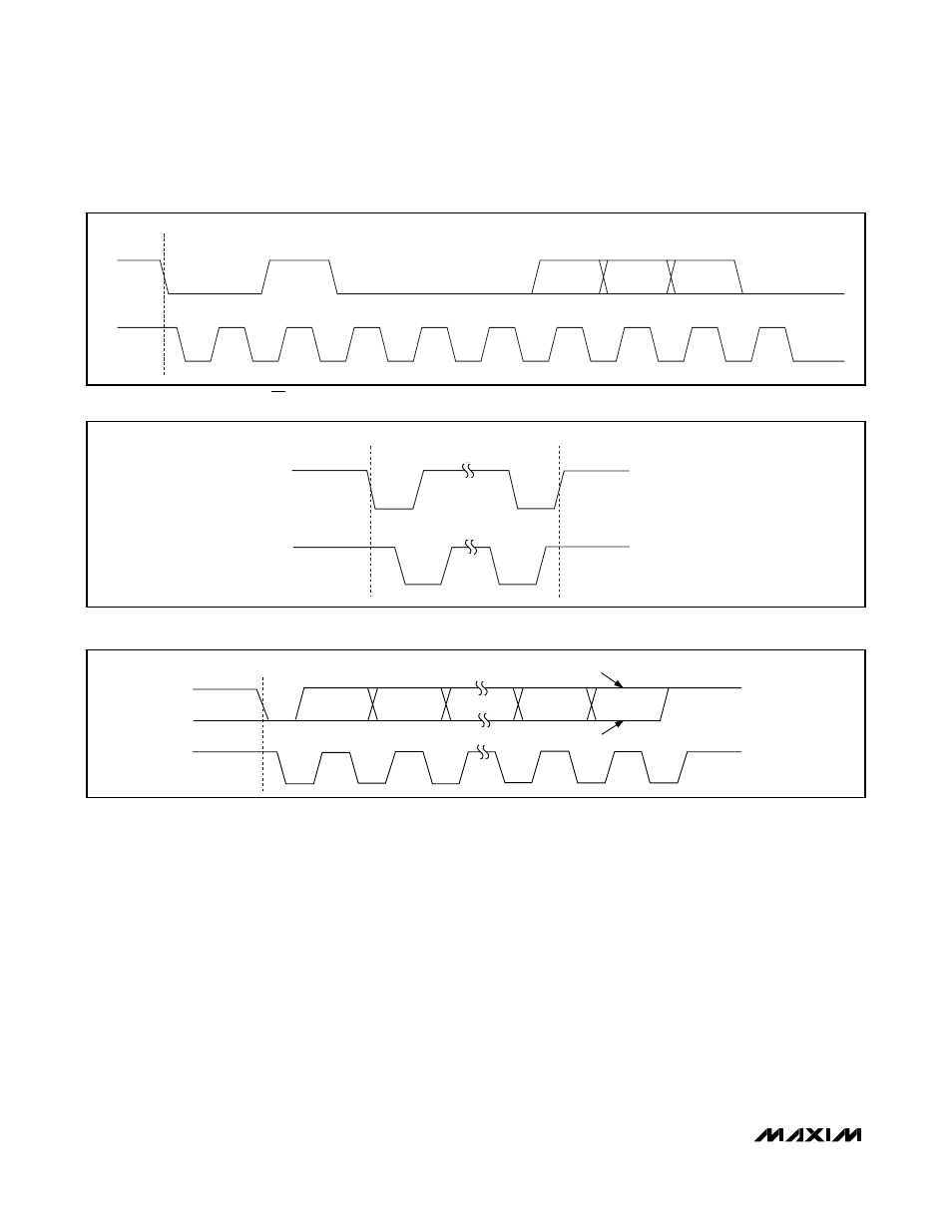
Figure 6. Slave Address and R/W Bit
SCL
SDA
S
P
Figure 7. START and STOP Conditions
SCL
SDA
S
1
2
8
9
NOT ACKNOWLEDGE
ACKNOWLEDGE
Figure 8. Acknowledge Bits