Max8759 low-cost, smbus, ccfl backlight controller – Rainbow Electronics MAX8759 User Manual
Page 15
MAX8759
Low-Cost, SMBus, CCFL Backlight Controller
______________________________________________________________________________________
15
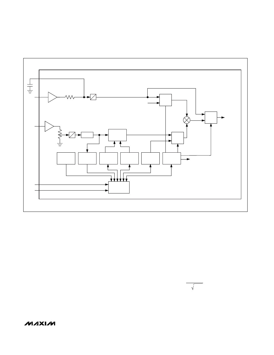
Figure 3. MAX8759 SMBus and Ambient-Light-Sensor Input Block
ALS
STATUS
REGISTER
ALS
LOW-LIMIT
REGISTER
ALS
HIGH-LIMIT
REGISTER
ALS
CLAMP
BRIGHT
CONTROL
REGISTER
DEVICE
CONTROL
REGISTER
MUX
DIGITAL
MULTIPLIER
BUFFER
DIGITAL
POT
SMBus
INTERFACE
DPWM
SETTING
PWMI
SDA
SCL
0X04
0X00
0X01
0X06
0X05
MUX
"1"
PWMO
ALS
SMBus AND AMBIENT-LIGHT-SENSOR INPUT BLOCK
INVERTER
ON/OFF
MUX
PWM_SEL
ALS_CTL
PWM_MD
BUFFER
FAULT/
STATUS
REGISTER
0X02
OFFSET
A
D
A
D
A simplified CCFL inverter circuit is shown in Figure 5
(a). The full-bridge power stage is simplified and repre-
sented as a square-wave AC source. The resonant tank
circuit can be further simplified to Figure 5(b) by
removing the transformer. C
S
is the primary series
capacitor, C
S
’ is the series capacitance reflected to the
secondary, C
P
is the secondary parallel capacitor, N is
the transformer turns ratio, L is the transformer sec-
ondary leakage inductance, and R
L
is an idealized
resistance that models the CCFL in normal operation.
Figure 6 shows the frequency response of the resonant
tank’s voltage gain under different load conditions. The
primary series capacitor is 1µF, the secondary parallel
capacitor is 15pF, the transformer turns ratio is 1:93,
and the secondary leakage inductance is 260mH.
Notice that there are two peaks, f
S,
and f
P
, in the fre-
quency response. The first peak f
S
is the series reso-
nant peak determined by the secondary leakage
inductance (L) and the series capacitor reflected to the
secondary (C’
S
):
f
1
2
LC
S
S
=
′
π