Rainbow Electronics MAX5559 User Manual
Page 13
MAX5556–MAX5559
Low-Cost Stereo Audio DACs
______________________________________________________________________________________
13
The MAX5558 accepts 16 bits of data in external serial
clock mode and internal serial clock mode. Program the
MCLK/LRCLK ratio to 384 to operate the internal serial
clock at 48 x f
S
. Program the MCLK/LRCLK ratio to 256
or 512 to operate the internal serial clock at 32 x f
S
.
MAX5559 18-Bit Right-Justified Data Format
The MAX5559 accepts data with an 18-bit right-justified
data format. The LSB is valid on the final SCLK rising
edge prior to LRCLK transitioning low to high or high to
low (Figure 7). In external serial clock mode, the
MAX5559 requires a minimum of 36 SCLK cycles per
LRCLK period (18 SCLK cycles with LRCLK low and 18
SCLK cycles with LRCLK high). Drive LRCLK high to
direct data to OUTL. Drive LRCLK low to direct data to
OUTR. Any additional SDATA bits prior to the MSB
are ignored.
The MAX5559 accepts 18 bits of data in external serial
clock mode and internal serial clock mode. Program the
MCLK/LRCLK ratio to 384 to operate the internal serial
clock at 48 x f
S
. Program the MCLK/LRCLK ratio to 256
or 512 to operate the internal serial clock at 64 x f
S
.
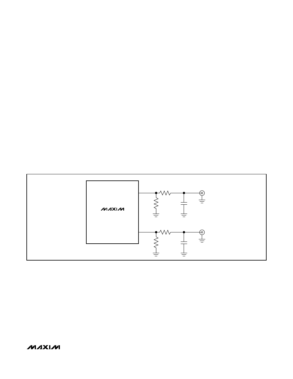
External Analog Filter
Use an external lowpass analog filter to further reduce
harmonic images, noise, and spurs. The external ana-
log filter can be either active or passive depending
upon performance and design requirements. For exam-
ple filters, see Figures 11 and 12 and the
Applications
Information
section. Careful attention should be paid
when selecting capacitors for audio signal path appli-
cations. NPO and C0G types are recommended as are
aluminum electrolytics and some tantalum varieties.
Use of generic ceramic types is not recommended and
may result in degraded THD performance. Always con-
sult manufacturers’ data sheets and applications infor-
mation.
MAX5556–MAX5559
OUTR
OUTL
100kΩ
100kΩ
R = 560Ω
R = 560Ω
C = 1.5nF
C = 1.5nF
Figure 11. Passive Component Analog Output Filter