Applications information – Rainbow Electronics MAX5515 User Manual
Page 17
MAX5512–MAX5515
Dual, Ultra-Low-Power,
8-Bit, Voltage-Output DACs
______________________________________________________________________________________
17
Applications Information
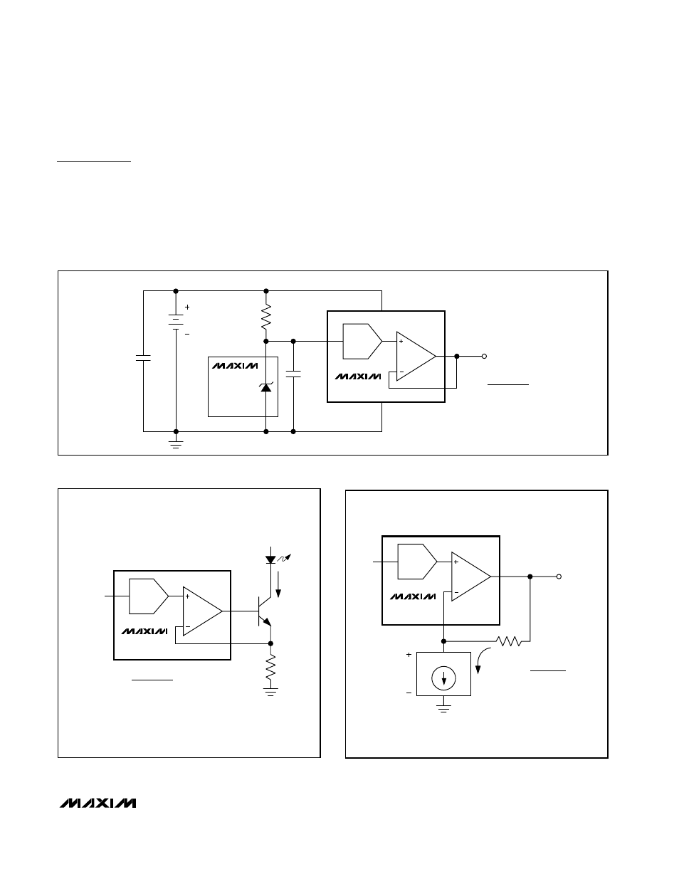
1-Cell and 2-Cell Circuits
See
Figure
3 for an illustration of how to power the
MAX5512–MAX5515 with either one lithium-ion battery
or two alkaline batteries. The low current consumption
of the devices make the MAX5512–MAX5515 ideal for
battery-powered applications.
Programmable Current Source
See the circuit in
Figure
4 for an illustration of how to
configure the MAX5514/MAX5515 as a programmable
current source for driving an LED. The MAX5514/
MAX5515 drive a standard NPN transistor to program
the current source. The current source (I
LED
) is defined
in the equation in
Figure
4.
REFIN
1/2 MAX5514
MAX6006
(1µA, 1.25V
SHUNT
REFERENCE)
GND
+1.25V
0.01µF
536kΩ
V
DD
DAC
VOUT
N
DAC
IS THE NUMERIC VALUE
OF THE DAC INPUT CODE.
V
OUT
(4.88mV / LSB)
1.8V ≤ V
ALKALINE
≤ 3.3V
2.2V ≤ V
LITHIUM
≤ 3.3V
V
OUT
=
V
REFIN
× N
DAC
256
0.1µF
Figure
3. Portable Application Using Two Alkaline Cells or One Lithium Coin Cell
R
2N3904
N
DAC
IS THE NUMERIC VALUE
OF THE DAC INPUT CODE.
I
LED
REFIN
LED
1/2 MAX5514
V+
DAC
VOUT
I
LED
=
V
REFIN
× N
DAC
256 × R
FB
Figure
4. Programmable Current Source Driving an LED
R
FB
N
DAC
IS THE NUMERIC VALUE
OF THE DAC INPUT CODE.
I
T
REFIN
1/2 MAX5514
DAC
VOUT
V
OUT
= V
BIAS
+ (I
T
× R)
V
OUT
V
BIAS
TRANSDUCER
V
BIAS
=
V
REF
× N
DAC
256
Figure
5. Transimpedance Configuration for a Voltage-Biased
Current-Output Transducer