Table 2. serial interface programming commands – Rainbow Electronics MAX5515 User Manual
Page 15
MAX5512–MAX5515
Dual, Ultra-Low-Power,
8-Bit, Voltage-Output DACs
______________________________________________________________________________________
15
Table
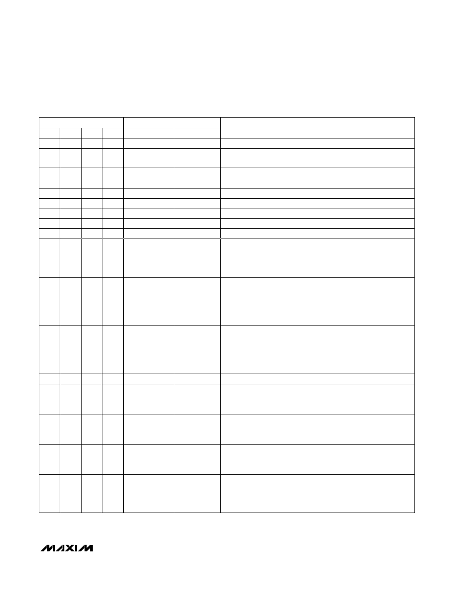
2. Serial Interface Programming Commands
CONTROL BITS
INPUT DATA
SUB-BITS
C3
C2
C1
C0
D7–D0
S3, S2, S1, S0
FUNCTION
0
0
0
0
XXXXXXXX
0000
No operation; command is ignored.
0
0
0
1
8-bit data
0000
Load input register A from shift register; DAC registers unchanged;
DAC outputs unchanged.
0
0
1
0
8-bit data
0000
Load input register B from shift register; DAC registers unchanged;
DAC outputs unchanged.
0
0
1
1
—
—
Command reserved. Do not use.
0
1
0
0
—
—
Command reserved. Do not use.
0
1
0
1
—
—
Command reserved. Do not use.
0
1
1
0
—
—
Command reserved. Do not use.
0
1
1
1
—
—
Command reserved. Do not use.
1
0
0
0
8-bit data
0000
Load DAC registers A and B from respective input registers; DAC
outputs A and B updated; MAX5513/MAX5515 enter normal
operation if in standby or shutdown; MAX5512/MAX5514 enter
normal operation if in shutdown.
1
0
0
1
8-bit data
0000
Load input register A and DAC register A from shift register; DAC
output A updated; Load DAC register B from input register B; DAC
output B updated; MAX5513/MAX5515 enter normal operation if in
standby or shutdown; MAX5512/MAX5514 enter normal operation
if in shutdown.
1
0
1
0
8-bit data
0000
Load input register B and DAC register B from shift register; DAC
output B updated; Load DAC register A from input register A; DAC
output A updated; MAX5513/MAX5515 enter normal operation if in
standby or shutdown; MAX5512/MAX5514 enter normal operation
if in shutdown.
1
0
1
1
—
—
Command reserved. Do not use.
1
1
0
0
D7, D6,
XXXXXX
0000
MAX5513/MAX5515 enter standby*, MAX5512/MAX5514 enter
shutdown. For the MAX5513/MAX5515, D7 and D6 configure the
internal reference voltage (Table 3).
1
1
0
1
D7, D6,
XXXXXX
0000
MAX5512–MAX5515 enter normal operation; DAC outputs reflect
existing contents of DAC registers. For the MAX5513/MAX5515,
D7 and D6 configure the internal reference voltage (Table 3).
1
1
1
0
D7, D6,
XXXXXX
0000
MAX5512–MAX5515 enter shutdown; DAC outputs set to high
impedance. For the MAX5513/MAX5515, D7 and D6 configure the
internal reference voltage (Table 3).
1
1
1
1
8-bit data
0000
Load input registers A and B and DAC registers A and B from shift
register; DAC outputs A and B updated; MAX5513/MAX5515 enter
normal operation if in standby or shutdown; MAX5512/MAX5514
enter normal operation if in shutdown.
X = Don’t care.
*Standby mode can be entered from normal operation only. It is not possible to enter standby mode from shutdown.