Chip information, Overdriving the inputs, Battery-operated infrared data link – Rainbow Electronics MAX9109 User Manual
Page 7
MAX9107/MAX9108/MAX9109
25ns, Dual/Quad/Single, Low-Power,
TTL Comparators
_______________________________________________________________________________________
7
V
TRIP+
V
HYST
V
TRIP-
V
IN+
COMPARATOR
OUTPUT
V
OH
V
OL
V
TRIP+
+ V
TRIP-
2
V
OS
=
V
IN-
= 0
Figure 1. Input and Output Waveforms, Noninverting Input
Varied
possible. Pay close attention to the decoupling capaci-
tor’s bandwidth, keeping leads short. Short lead
lengths on the inputs and outputs are also essential to
avoid unwanted parasitic feedback around the com-
parators. Solder the device directly to the printed circuit
board instead of using a socket.
Overdriving the Inputs
The inputs to the MAX9107/MAX9108/MAX9109 may be
driven to the voltage limits given in the Absolute
Maximum Ratings. If the inputs are overdriven, there is
no output phase reversal.
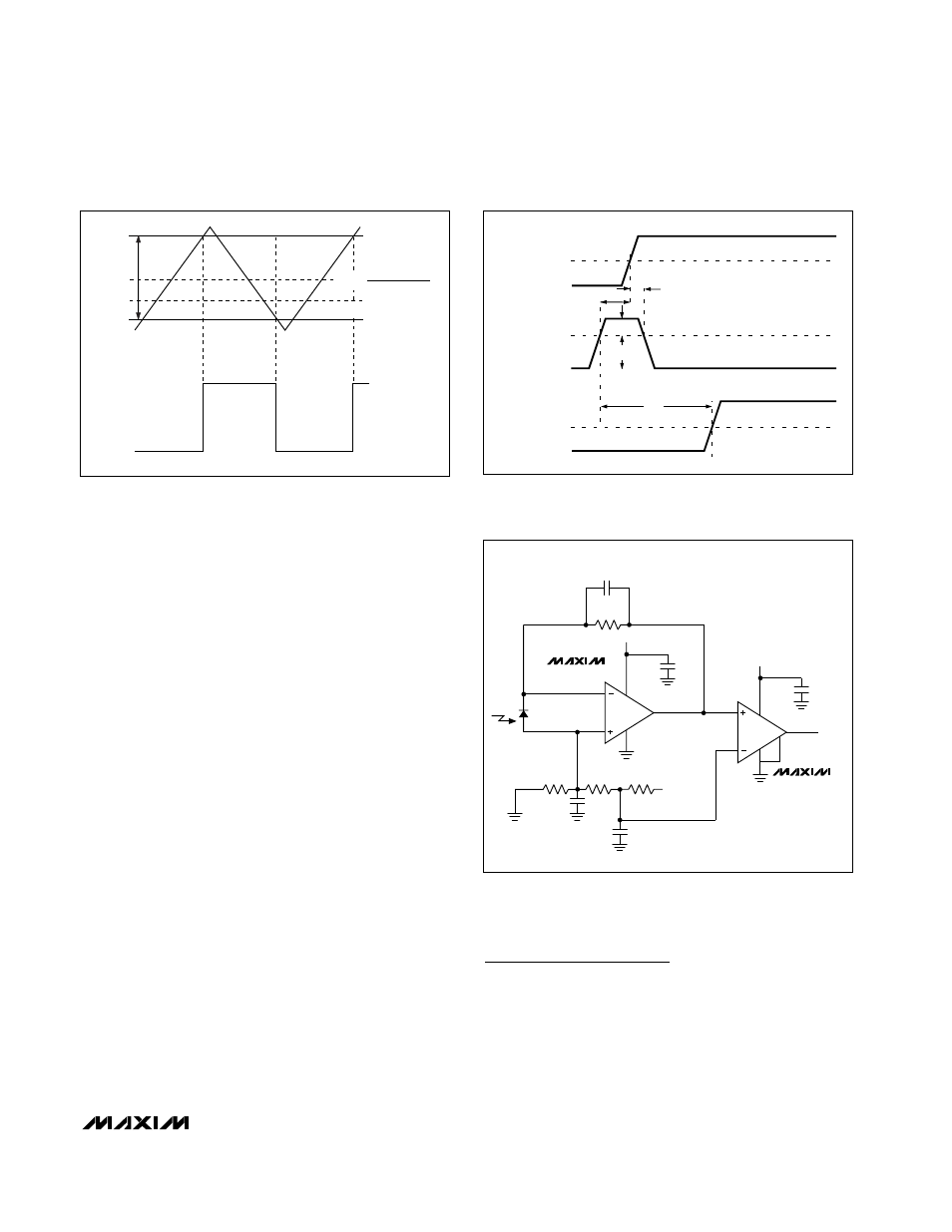
Battery-Operated Infrared Data Link
In Figure 3, the circuit allows reception of infrared data.
The MAX4400 converts the photodiode current to a
voltage, and the MAX9109 determines whether the
amplifier output is high enough to be called a “1.” The
current consumption of this circuit is minimal: the
MAX4400 and MAX9109 require typically 410µA and
350µA, respectively.
t
PD
+
V
IN
V
OD
t
h
t
s
3V
1.4V
0
V
OS
V
OH
1.4V
V
OL
COMPARE
LATCH
LE
DIFFERENTIAL
INPUT
VOLTAGE
OUTPUT
Figure 2. MAX9109 Timing Diagram
10pF
1M
Ω
+5V
4
5
+5V
0.1
µF
DATA
4
3
100k
Ω
SIEMENS BP-104
PHOTODIODE
100k
Ω
+5V
1000pF
1000pF
47k
Ω
3
1
0.1
µF
2
6
1
MAX9109
MAX4400
2
5
Figure 3. Battery-Operated Infrared Data Link Consumes Only
760µA
Chip Information
MAX9107 TRANSISTOR COUNT: 262
MAX9108 TRANSISTOR COUNT: 536
MAX9109 TRANSISTOR COUNT: 140
PROCESS: Bipolar