Rainbow Electronics MAX5133 User Manual
Page 11
MAX5132/MAX5133
+5V/+3V, 13-Bit, Serial, Force/Sense DACs
with 10ppm/°C Internal Reference
______________________________________________________________________________________
11
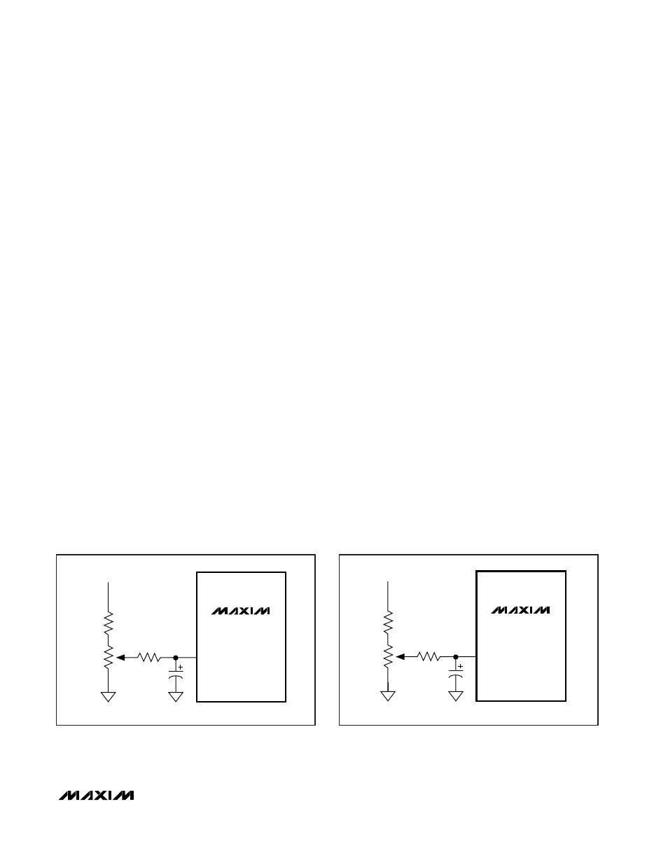
operation of the DAC. Larger capacitor values may be
used but will result in increased start-up delay. The
time constant
τ
for the start-up delay is determined by
the REFADJ input impedance of 4k
Ω
and C
REFADJ
:
τ
= 4k
Ω
·
C
REFADJ
External Reference
An external reference may be applied to the REF pin.
Disable the internal reference by pulling REFADJ to
V
DD
. This allows an external reference signal (AC- or
DC-based) to be fed into the REF pin. For proper oper-
ation,
do not
exceed the input voltage range limits of
0V to (V
DD
- 1.4V) for V
REF
.
Determine the output voltage using the following equa-
tion (REFADJ = V
DD
):
V
OUT
= V
REF
(NB / 8192)G
where NB is the numeric value of the MAX5132/
MAX5133 input code (0 to 8191), V
REF
is the external
reference voltage, and G is the gain of the output
amplifier, set by an external resistor-divider. The REF
pin has a minimum input resistance of 40k
Ω
and is
code dependent.
Output Amplifier
The MAX5132/MAX5133’s DAC output is internally
buffered by a precision amplifier with a typical slew rate
of 0.6V/µs. Access to the output amplifier’s inverting
input (FB) provides the user greater flexibility with
amplifier gain setting and signal conditioning (see
Applications Information
).
The output amplifier typically settles to ±0.5LSB from a
full-scale transition within 20µs when it is connected in
unity gain and loaded with 5k
Ω
100pF. Loads less
than 1k
Ω
may result in degraded performance.
Power-Down Mode
The MAX5132/MAX5133 feature software- and hard-
ware-programmable (PD pin) shutdown modes that
reduce the typical supply current to 3µA. To enter soft-
ware shutdown mode, program the control sequence
for the DAC as shown in Table 1.
In shutdown mode, the amplifier output becomes
high impedance and the serial interface remains active.
Data in the input registers is saved, allowing the
MAX5132/MAX5133 to recall the output state prior to
entering shutdown when returning to normal operation.
To exit shutdown mode, load both input and DAC regis-
ters simultaneously or update the DAC register from the
input register. When returning from shutdown to normal
operation, wait 2ms for the reference to settle. When
using an external reference, the DAC requires only
20µs for the output to stabilize.
Power-Down Lockout Input (
PDL
)
The power-down lockout (PDL) pin disables shutdown
when low. When in shutdown mode, a high-to-low tran-
sition on PDL will wake up the DAC with its output still
set to the state prior to power-down. PDL can also be
used to wake up the device asynchronously.
Power-Down Input (PD)
Pulling PD high places the MAX5132/MAX5133 in shut-
down. Pulling PD low will not return the MAX5132/
MAX5133 to normal operation. A high-to-low transition
on PDL or appropriate commands (Table 1) via the ser-
ial interface are required to exit power-down.
REFADJ
+3V
15k
100k
400k
33nF
MAX5133
REFADJ
+5V
90k
100k
400k
33nF
MAX5132
Figure 3a. MAX5132 Reference Adjust Circuit
Figure 3b. MAX5133 Reference Adjust Circuit