Detailed description, Hysteresis selection, Applications information – Rainbow Electronics MAX6508 User Manual
Page 5: Selection table
MAX6505–MAX6508
Dual Trip SOT Temperature Switches
_______________________________________________________________________________________
5
_______________Detailed Description
The MAX6505–MAX6508 fully integrated temperature
switches incorporate two temperature-dependent refer-
ences and a comparator. One reference exhibits a pos-
itive temperature coefficient and the other a negative
temperature coefficient. The temperature at which the
two reference voltages are equal determines the tem-
perature trip point. There are two versions, each of
which has two logic outputs.
The MAX6505/MAX6506 have a main trip point (T
ALARM
)
and a lower, “warning” trip point (T
WARN
). When the die
temperature rises above these trip points, the ALARM
and WARN outputs are asserted (Figure 1). The differ-
ence between the two trip points (
∆T
AW
) is pin selec-
table to +5°C, +10°C, +20°C, or +30°C by connecting
the two control pins (S0 and S1) high or low (Table 1).
MAX6505 has open-drain active-low outputs; MAX6506
has push-pull active-high outputs.
The MAX6507/MAX6508 have two factory-programmed
threshold temperatures (T
OVER
and T
UNDER
) and two
outputs (OK and OVER). One output (OK) asserts
when the temperature is between T
OVER
and T
UNDER
.
The other output (OVER) asserts when the temperature
is above T
OVER
. Table 4 shows the hex codes to deter-
mine the part numbers associated with specific values
of T
OVER
and T
UNDER
. The first hex code indicates the
lower trip point (T
UNDER
) and the second indicates the
higher trip point (T
OVER
). For example, a part with T
UN-
DER
= -10°C and T
OVER
= +75°C will have the part
number MAX6508UTA04B (Table 4 and Figure 2).
MAX6507 has open-drain outputs; MAX6508 has push-
pull outputs.
Hysteresis Selection
The temperature threshold hysteresis for the ALARM
output of the MAX6505/MAX6506 is 2°C. The hysteresis
for the WARN output depends on the value of
∆T
AW
. If
∆T
AW
is 5°C or 10°C (set by S0 and S1), WARN hys-
teresis is 5°C. If
∆T
AW
is 20°C or 30°C, WARN hystere-
sis is 10°C. MAX6507 and MAX6508 have pin-selectable
hysteresis of 2°C or 10°C for both OVER and OK out-
puts (Table 2).
Applications Information
Thermal Considerations
The MAX6505–MAX6508 supply current is typically
30µA. When used to drive high-impedance loads, the
devices dissipate negligible power. Therefore, the die
temperature is essentially the same as the package
temperature. The key to accurate temperature monitor-
ing is good thermal contact between the MAX6505–
MAX6508 package and the device being monitored. In
some applications, the SOT23-6 packages may be
small enough to fit underneath a socketed micro-
processor (µP), allowing the device to monitor the µP’s
temperature directly. Use the monitor’s output to reset
the µP, assert an interrupt, or trigger an external alarm.
Accurate temperature monitoring depends on the ther-
mal resistance between the device being monitored
and the MAX6505–MAX6508 die.
The rise in die temperature due to self-heating is given
by the following formula:
∆T
J
= P
DISSIPATION
✕
θ
JA
where P
DISSIPATION
is the power dissipated by the
MAX6505–MAX6508, and
θ
JA
is the package’s thermal
resistance. The typical thermal resistance is +115°C/W
for the SOT23-6 package. To limit the effects of self-heat-
ing, minimize the output currents. For example, if the
MAX6505 sinks 5mA, the output voltage is guaranteed to
be less than 0.5V. Therefore, an additional 2.5mW of
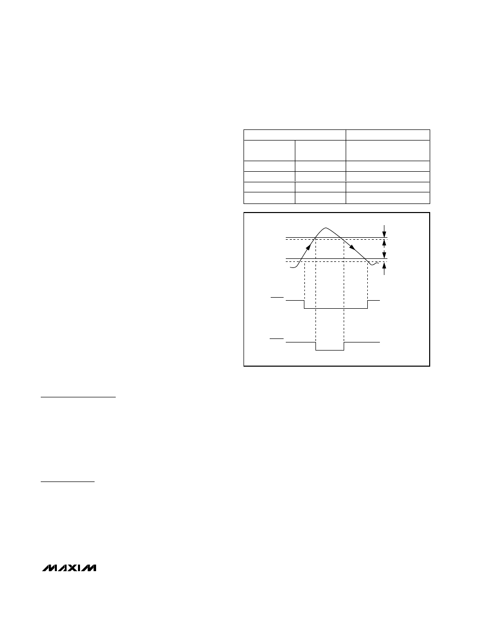
Figure 1. Temperature Response—MAX6505UTP065 Outputs,
∆T
AW
= 10°C, and WARN Hysteresis
≈ 5°C
HYSTERESIS
≈ 2°C
HYSTERESIS
≈ 5°C
65°C
55°C
WARN
ALARM
Table 1. MAX6505/MAX6506
∆T
AW
Selection Table
CONTROL PINS
DESCRIPTION
S0
S1
∆T
AW
=T
ALARM
– T
WARN
(
°C)
GND
GND
5
GND
V
CC
10
V
CC
GND
20
V
CC
V
CC
30