Typical operating characteristics (continued), Pin description – Rainbow Electronics MAX16055 User Manual
Page 5
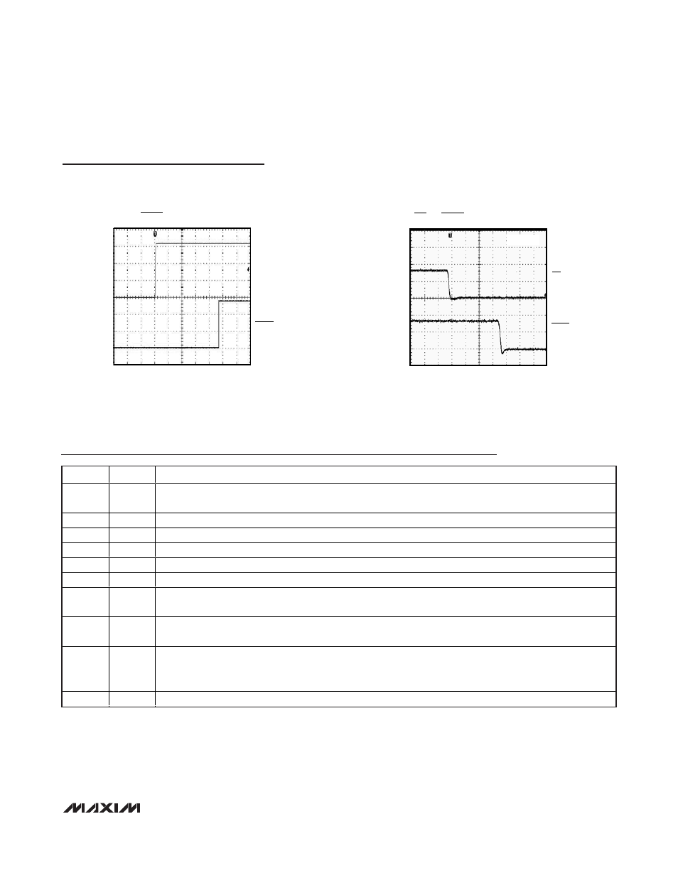
RESET TIMEOUT DELAY
MAX16055 toc09
IN_
1V/div
RESET
1V/div
40ms/div
MR-TO-RESET PROPAGATION DELAY
MAX16055 toc10
MR
2V/div
RESET
2V/div
40ns/div
V
IN
= 3.3V
MAX16055
Ultra-Small, Hex Voltage,
Microprocessor Supervisor
_______________________________________________________________________________________
5
Typical Operating Characteristics (continued)
(V
IN1
= 3.3V, T
A
= +25°C, unless otherwise noted.)
Pin Description
PIN
NAME
FUNCTION
1
IN1
Voltage Input 1. IN1 is the power-supply input and voltage monitoring input for the device. Connect a 0.1µF
bypass capacitor from IN1 to GND. Keep IN1 or IN2 > 1V to ensure RESET is valid.
2
IN2
Voltage Input 2. See the Selector Guide for voltage threshold. Keep IN1 or IN2 > 1V to ensure RESET is valid.
3
IN3
Voltage Input 3. See the Selector Guide for voltage threshold.
4
IN4
Voltage Input 4. See the Selector Guide for voltage threshold.
5
IN5
Voltage Input 5. See the Selector Guide for voltage threshold.
6
IN6
Voltage Input 6. See the Selector Guide for voltage threshold.
7
TOL
Threshold Tolerance Input. Connect TOL to GND to select thresholds 5% below nominal. Connect TOL to IN1
to select thresholds 10% below nominal.
8
MR
Active-Low Manual-Reset Input. When MR is low, RESET goes low and remains asserted for the reset timeout
period after MR is pulled high. MR is internally pulled high by a 20k
Ω pullup resistor to IN1.
9
RESET
Active-Low Reset Output. RESET goes low when any input (IN_) goes below the specified threshold. After all
inputs rise above the specified threshold voltages, RESET remains low for 140ms (min) before going high.
The open-drain RESET output features a weak (70µA) internal pullup to IN1.
10
GND
Ground