Max9890, Audio click-pop suppressor – Rainbow Electronics MAX9890 User Manual
Page 8
MAX9890
ness (on-resistance flatness is defined as the difference
between the maximum and minimum values of on-resis-
tance measured over the specific analog-signal range).
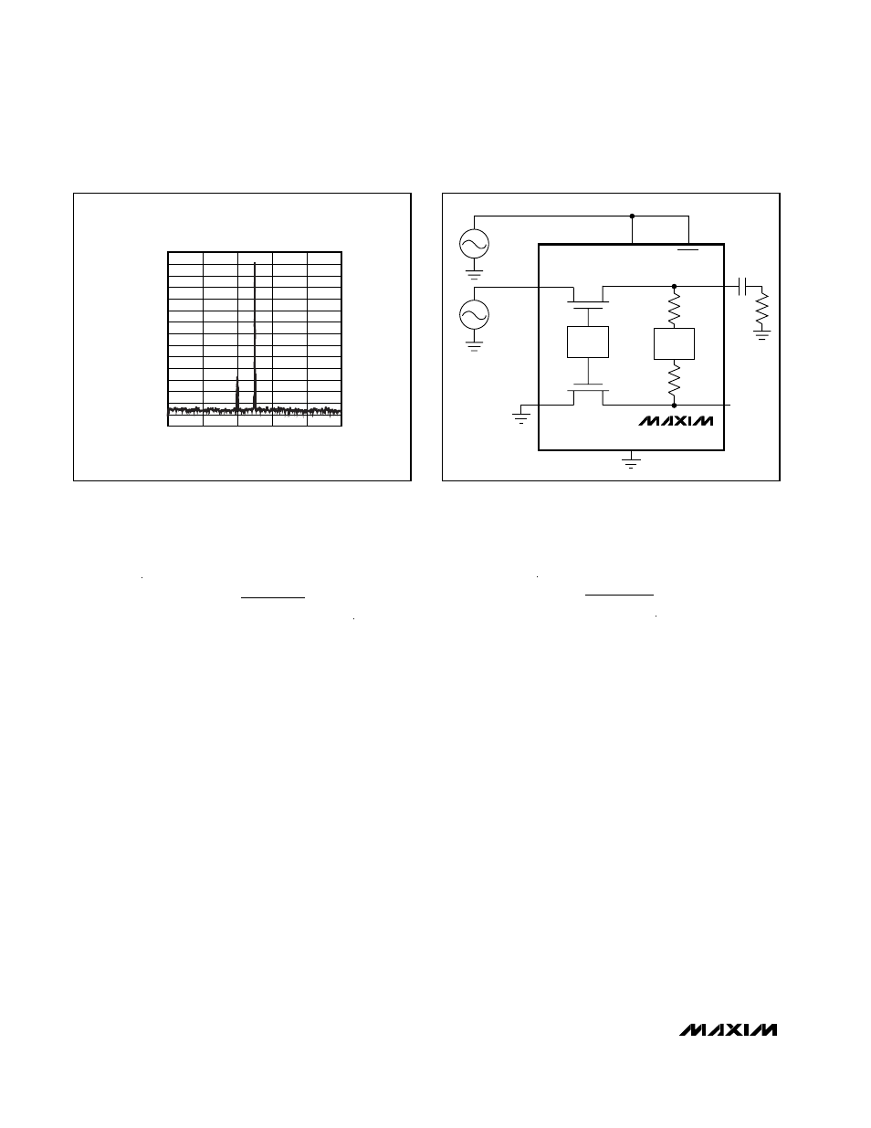
Power-Supply Rejection Ratio (PSRR)
PSRR is the measurement of AC power-supply ripple or
noise that couples to the output. Variations in supply volt-
age corrupt the audio signal, due to changes in the R
ON
value by supply modulation. The FFT shown in Figure 5
was taken with a 19kHz 1V
P-P
sine wave onto the 5V DC
supply voltage, and a 20kHz 1V
P-P
sine wave applied at
IN_ with a 32
Ω load is shown in Figure 6. The MAX9890
maintains a -100dB (typ) PSRR across the supply voltage
range eliminating any corruption of the audio signal from
supply variations. Therefore, with a zero audio signal, the
R
ON
variation due to supply voltage ripple does not con-
tribute to any output signal modulation.
Low-Frequency Response
In addition to the cost and size disadvantages of the
output-coupling capacitors, these capacitors limit the
amplifier’s low-frequency response and can distort the
audio signal.
The impedance of a headphone or speaker load and
the output-coupling capacitor form a highpass filter with
the -3dB point set by:
where R
L
is the headphone impedance and C
OUT
is
the output-coupling capacitor value. The highpass filter
is required by conventional single-ended, single power-
supply headphone drivers to block the midrail DC bias
component of the audio signal from the headphones.
The drawback to the filter is that it can attenuate low-
frequency signals. Larger values of C
OUT
reduce this
effect but result in physically larger, more expensive
capacitors. Figure 7 shows the relationship between the
size of C
OUT
and the resulting low-frequency attenua-
tion. Note that the -3dB point for a 16
Ω headphone with
a 100µF blocking capacitor is 100Hz, well within the
normal audio band, resulting in low-frequency attenua-
tion of the reproduced signal.
The MAX9890A and MAX9890B have different turn-on
times to accommodate different size output-coupling
capacitors (see Table 1). Using a capacitor smaller
than the specified maximum allowed does not degrade
click-pop suppression. Therefore, capacitors less than
100µF can be used with the A or B version devices.
f
R C
dB
L OUT
−
=
3
1
2
π
THD
R
R
MAXIMUM
FLAT ON
LOAD
=
×
(
)
%
4
100
Audio Click-Pop Suppressor
8
_______________________________________________________________________________________
-140
-70
-80
-90
-100
-110
-120
-130
-50
-60
-30
-40
-20
0
-10
10
15
17
19
21
23
25
V
CC
= 4.5V TO 5.5V, f
VCC
= 19kHz,
R
L
= 32
Ω, V
IN
= 1V
P-P
, f
IN
= 20kHz
FREQUENCY (kHz)
OUTPUT SPECTRUM (dBV)
Figure 5. FFT for PSRR
RAMP
UP
V
DC
= 5V
V
AC
= 1V
P-P
19kHz
V
DC
= 2.0V
V
AC
= 1V
P-P
20kHz
SHDN
MAX9890
IN_
IN_
OUT_
R
L
OUT_
RAMP
DOWN
V
CC
Figure 6. PSRR Test Circuit