Table 1. serial-interface programming commands – Rainbow Electronics MAX5151 User Manual
Page 10
MSB
LSB
MAX5150/MAX5151
puts become high impedance, and the serial inter-
face
remains active. Data in the input registers is
saved, allowing the MAX5150/MAX5151 to recall the
output state prior to entering shutdown when returning
to normal mode. Exit shutdown by recalling the previ-
ous condition or by updating the DAC with new infor-
mation. When returning to normal operation (exiting
shutdown), wait 20µs for output stabilization.
Serial Interface
The MAX5150/MAX5151 3-wire serial interface is com-
patible with both Microwire (Figure 2) and SPI/QSPI
(Figure 3) serial-interface standards. The 16-bit serial
input word consists of an address bit, two control bits,
and 13 bits of data (MSB to LSB) as shown in Figure 4.
Low-Power, Dual, 13-Bit Voltage-Output DACs
with Serial Interface
10
______________________________________________________________________________________
16-BIT SERIAL WORD
FUNCTION
A0
C1
C0
D12.......................D0
(MSB) (LSB)
0 0 1
13-bit DAC data
Load input register A; DAC registers are unchanged.
0 1 1
13-bit DAC data
Load all DAC registers from the shift register
(start up both DACs with new data.).
1 1 0
13-bit DAC data
Load input register B; all DAC registers are updated.
0 1 0
13-bit DAC data
Load input register A; all DAC registers are updated.
1 0 1
13-bit DAC data
Load input register B; DAC registers are unchanged.
0 0 0
1 1 0 x xxxxxxxxx
Shut down DAC A (provided PDL = 1).
0 0 0
1 0 1 x xxxxxxxxx
Update DAC register B from input register B
(start up DAC B with data previously stored in input register B).
0 0 0
0 0 1 x xxxxxxxxx
Update DAC register A from input register A
(start up DAC A with data previously stored in input register A).
1 1 1
xxxxxxxxxxxxx
Shut down both DACs (provided PDL = 1).
1 0 0
xxxxxxxxxxxxx
Update both DAC registers from their respective input registers
(start up both DACs with data previously stored in the input registers).
0 0 0
1 1 1 x xxxxxxxxx
Shut down DAC B (provided PDL = 1).
0 0 0
0 1 0 x xxxxxxxxx
UPO goes low (default).
0 0 0
0 1 1 x xxxxxxxxx
UPO goes high.
0 0 0
1 0 0 1 xxxxxxxxx
Mode 1, DOUT clocked out on SCLK’s rising edge.
0 0 0
1 0 0 0 xxxxxxxxx
Mode 0, DOUT clocked out on SCLK’s falling edge (default).
0 0 0
0 0 0 x xxxxxxxxx
No operation (NOP).
Table 1. Serial-Interface Programming Commands
x = Don’t care
Note: When A0, C1, and C0 = 0, then D12, D11, D10, and D9 become control bits.
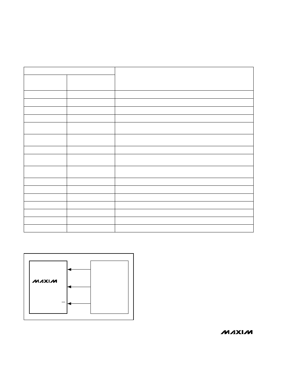
SCLK
DIN
CS
SK
SO
I/O
MAX5150
MAX5151
MICROWIRE
PORT
Figure 2. Connections for Microwire