Overview, Control board – rear gfx01 – front – TC Electronic G-System User Manual
Page 20
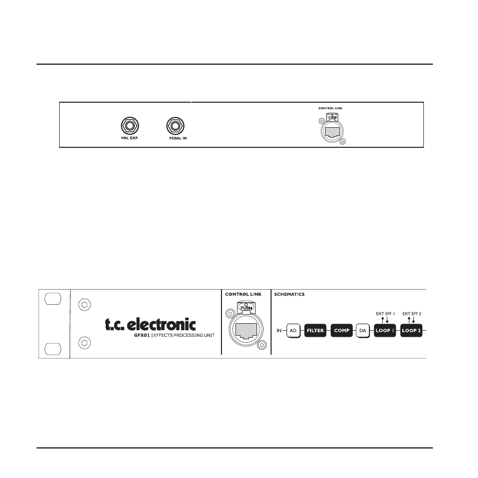
Control Board – Rear
GFX01 – Front
Control Link
Use a standard Cat 5 cable to connect the Control Board
to the GFX01. A short cable is already mounted upon
delivery when the G-System is assembled.
When you detach the GFX01 from the Control Board and
mount it in a rack, use a Cat 5 of suitable length (max.
15 meters).
There are three connectors on the Control Board.
When the G-System is assembled, the Control Link
connectors on the Control Board and on the GFX01 are
connected with a short Cat 5 cable.
When the GFX01 is mounted in a rack, a longer Cat 5
cable (not supplied) is used. Use a high quality Cat 5
cable with XLR housing for maximum stability.
Expression pedals can be connected to either the GFX01
(when the unit is assembled) or to the Control Board
when the GFX01 is mounted in a rack.
It is possible to connect two expression pedals to the
Control Board and at the same time connect two
expression pedals to the GFX01. This gives you two
“handles” for each of the parameters assigned to these
connectors, which you can place on stage where
required.
For more information on expression pedals, please refer
to the relevant sections of this manual.
OVERVIEW
18
We suggest using a “road-proof”, high quality Cat 5 cable
with XLR housing.