Operating instructions, 9121 function submenu list and descriptions – Cobalt Digital COMPASS 9121 3G_HD_SD-SDI_ASI Redundancy Switch User Manual
Page 25
9121-OM (V1.2)
9121 PRODUCT MANUAL
3-5
Operating Instructions
9121 Function Submenu List and Descriptions
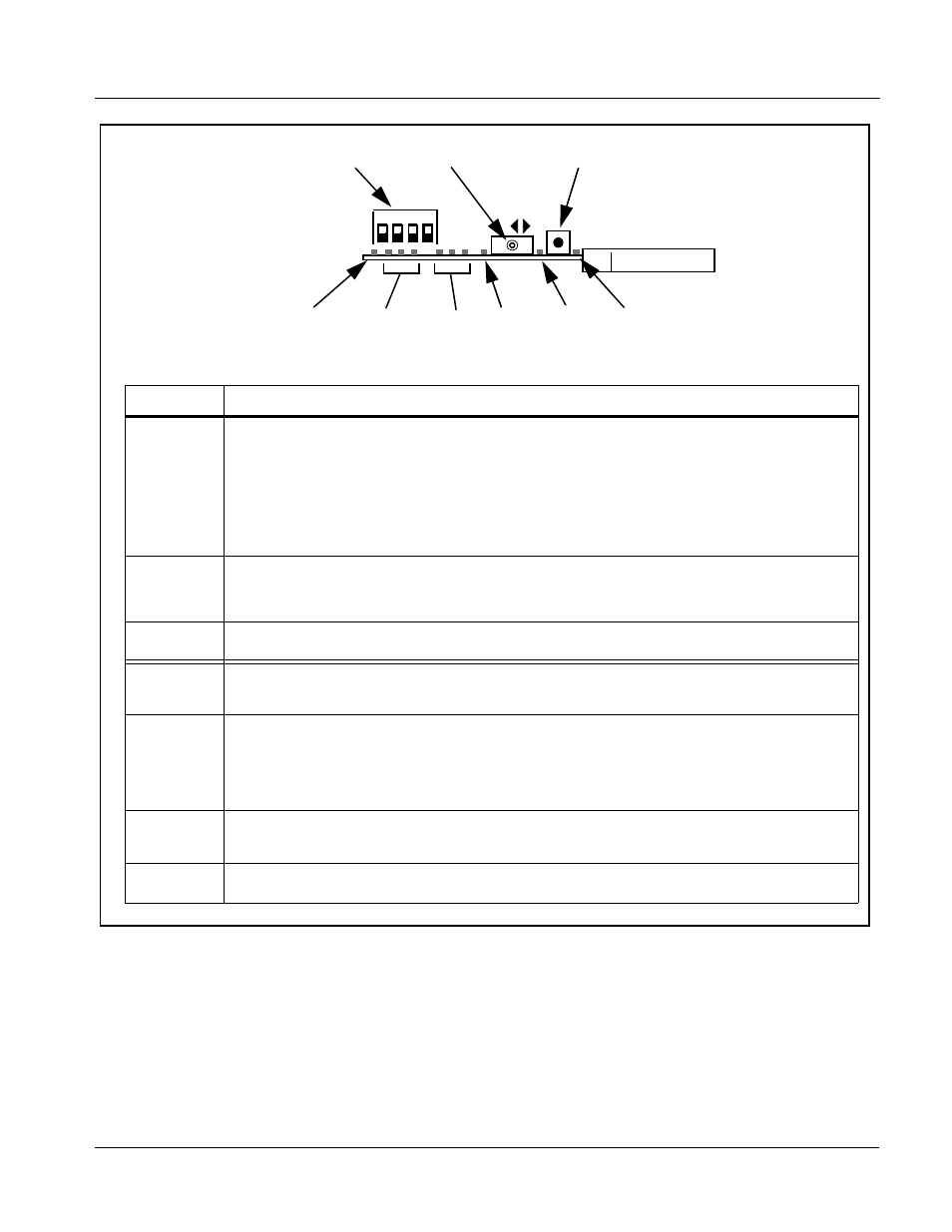
Figure 3-1 9121 Card Edge Controls and Indicators
9121
Item
Function
Mode/RCK
Select
switches
4-position piano switch selects the following:
• (1) UP – Card Edge Control Enabled (DashBoard disabled) –
DOWN – Card Edge Control Disabled (DashBoard enabled)
• (2) Reserved
• (3) UP – Input A Reclocking Disabled
DOWN – Input A Reclocking Enabled
• (4) UP – Input B Reclocking Disabled
DOWN – Input B Reclocking Enabled
Input Select
switch
After ARM button is pressed, allows input routing as follows:
• LEFT – select Input A
• RIGHT – select Input B
ARM
pushbutton
When pressed, allows input select as described above (times out after appr. 8 seconds)
Remote
(RMT) Status
indicator
When illuminated, remote control is enabled
Input A
Status
Input B
Status
indicators
Three blue LEDs indicate the input signal format being received and locked onto by the 9121:
• 3G
• HD
• SD
Continuous cycling of the LEDs indicates the 9121 has not locked onto a particular format (as in the case of no
signal input or unrecognized signal type).
A Sel
B Sel
indicators
Indicates input (A or B) currently routed to outputs
ARM Sel
indicator
Indicates Input Select switch is armed
Mode/RCK Select Switch
Input Select Switch
ARM Switch
Input A
Status
LEDs
Input B
Status
LEDs
A
Sel
LED
ARM
Sel
LED
Remote (RMT)
Status
LED
B
Sel
LED
A
B
1
2 3
4