Installing a rear i/o module, Installing a rear i/o module -2 – Cobalt Digital COMPASS 9121 3G_HD_SD-SDI_ASI Redundancy Switch User Manual
Page 16
2
Installing a Rear I/O Module
2-2
9121 PRODUCT MANUAL
9121-OM (V1.2)
Installing a Rear I/O Module
Install a Rear I/O Module as follows:
1.
On the frame, determine the slot in which the 9121 is to be installed.
2.
In the mounting area corresponding to the slot location, install
Rear I/O Module as shown in Figure 2-1.
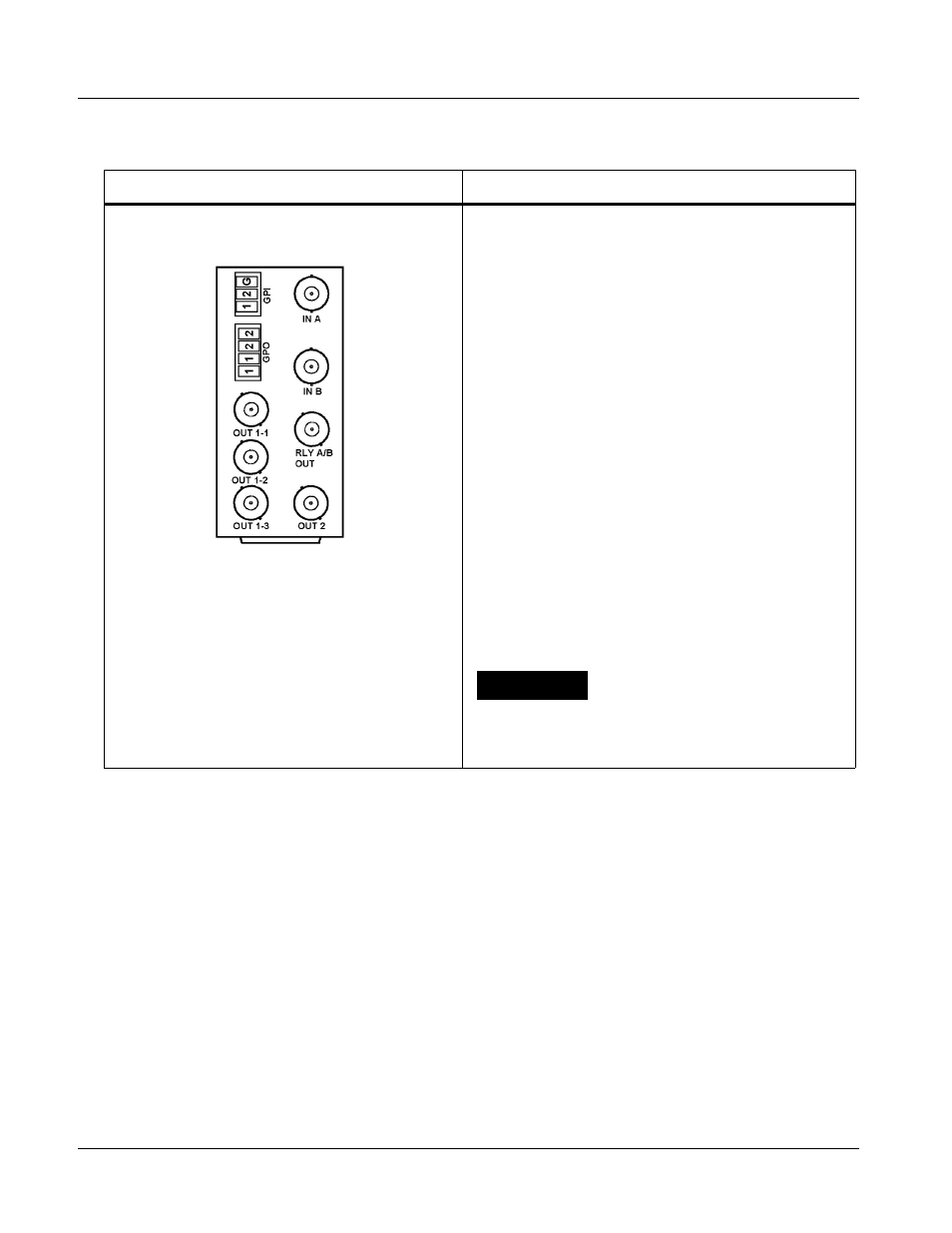
Table 2-1
9121 Rear I/O Modules
9121 Rear I/O Module
Description
RM20-9121-B
Provides the following connections:
• IN A BNC input
• IN B BNC input
• RLY A/B OUT passive relay-coupled output.
Failover to IN B if IN A is invalid. Manually selected
via user controls or SNMP.
Note: Relay output must be terminated into 75
Ω
impedance via connection to downstream
equipment or termination for card to properly
display input status.
• Four non-relay outputs (OUT 1-1, 1-2, 1-3, and
OUT 2) with defeatable reclocking. All four
non-relay outputs track with RLY A/B OUT
selection.
• GPI inputs GPI1/G and GPI2/G for manual
selection of inputs IN A or IN B.
- GPI 1 invokes IN A
- GPI 2 invokes IN B
• GPI outputs GPO1 and GPO2 indicate input
channel selection (either invoked manually or via
failover).
- GPO 1 pair closed when IN A is selected
- GPO 2 pair closed when IN B is selected
CAUTION
GPO controlled circuit must not exceed voltage/
current ratings. See Technical Specifications (p. 1-6)
in Chapter 1, Introduction.