Moog Music Etherwave Plus Kit (Upgrade Instructions) User Manual
Page 2
(1) LED spacer
(2) 1/4” TRS Jack assemblies w/ hardware: lockwasher, washer, and nut.
(1) power switch
(1) knob
(1) calibration tool
The Etherwave Plus Upgrade is divided into 4 basic parts:
• Disassembly of the Etherwave
• Drilling the holes for installing the 11-213 PCB assembly
• Installing the Upgrade
• Tuning and testing
Please read and understand all the steps below before proceeding.
A note about ESD
ESD stands for Electrostatic Discharge. Have you ever walked across a carpeted room, touched a light switch and
received a shock? This is a form of ESD. ESD is more common when the air is very dry, and static charges easily build up
on the body or clothing if you move around on carpeted or wood flooring.
ESD can damage electronic components such as Semiconductors and Integrated Circuits. You can discharge static
electricity into these types of components without feeling anything and still cause damage. Both of these types of compo-
nents are used on the 11-211 Etherwave circuit board and on the 11-213 Etherwave Plus circuit board.
Simple precautions can avoid damage to your circuits. Remember to touch a grounded surface before handling circuit
boards or components when they are outside of ESD-safe packaging. If you leave your work area and return, discharge
any static charge built up on your body by touching a grounded surface. Avoid touching the components on a circuit
board.
Disassembly of the Etherwave.
In order to drill holes in the bottom of the cabinet, it is necessary to disassemble the Etherwave. Save the screws
that are removed from the unit until it is re-assembled.
1) If necessary, disconnect the Etherwave from the power supply and remove the antennas.
2) Turn the Etherwave over, remove the three screws holding on the mic stand adapter.
3) Remove the 4 screws (2 each on the front and back) that fasten the cover and take the cover off the unit.
4) Unplug the front panel from connector CN1 on the PCB.
5) De-solder the bus wire connecting the PCB to the antennas’ hardware at the PCB, and remove the 5 screws
holding the Etherwave PCB in place. Remove the PCB and place somewhere safe and static-free.
6) Remove the three screws on the bottom of the cabinet fastening the front panel and remove the front panel.
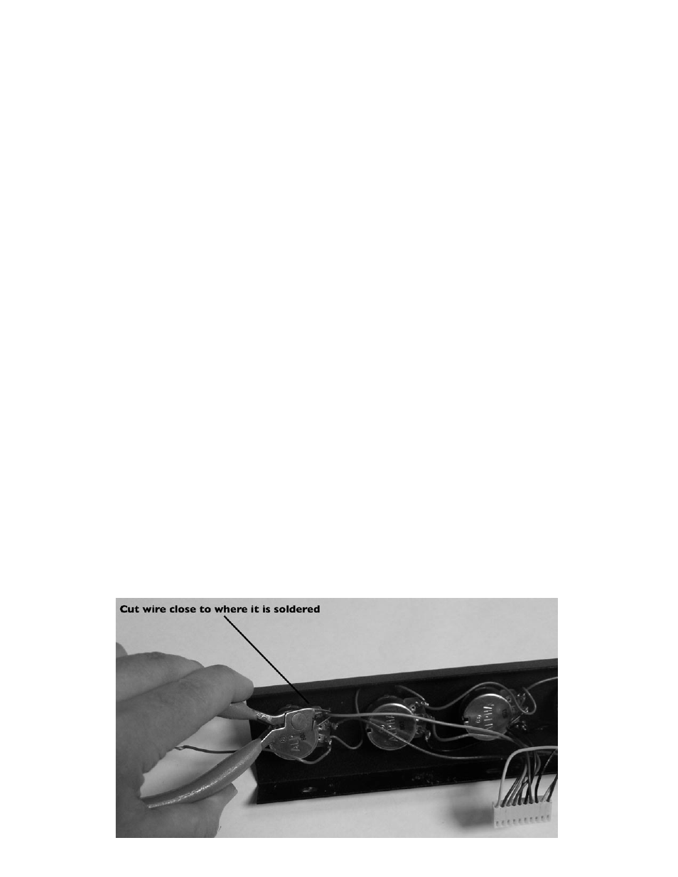
7) Disconnect the grey and white wires from the power switch. Cut the following wires where they are soldered to
the pots or jack: Yellow, Brown, Orange, Red, Violet, Blue, Green, Black. (see figure 1)
8) Once the 10-wire harness is disconnected from the front panel, cut all wires to match the length of the shortest
wires (blue and green are the shortest).
9) Remove the four knobs from the front panel by loosening their set screws with a 1/8” flathead screwdriver.
figure 1