Wilwood Tandem Master Cylinder User Manual
Page 2
Wilwood • Phone 805 / 388-1188
Fax 805 / 388-4938 • www.wilwood.com
E-mail Technical Assistance: [email protected]
Tandem Master Cylinders, Components and Accessories
Part No.
Description
260-4893
1-1/16" Bore Tandem Outlet Master Cylinder only
260-4894
1-1/16" Bore Tandem Outlet Master Cylinder with push rod, retainer, and boot
260-4896
1-1/16" Bore Master Cylinder Rebuild Kit
260-1874
2 Pound Residual Pressure Valve
260-1875
10 Pound Residual Pressure Valve
260-8419
Knob Adjustable Proportioning Valve
260-8420
Lever Adjustable Proportioning Valve
250-2406
Firewall Mount Reinforcement Plate
250-3677
Wilwood Pedal Adapter Plate Kit
340-1289
Floor Mount Pedal, 6:1 ratio
340-1290
Forward Swing Mount Pedal, 7:1 ratio
290-0632
Wilwood Hi-Temp 570 DOT 3 Fluid
290-6209
Wilwood EXP 600 Plus Super Hi-Temp Fluid
CALCULATING EFFECTIVE PISTON BORE AREA TO DETERMINE PLUMBING
To determine the effective piston bore area of any caliper, you must first calculate the area for each piston bore found on one side
of the caliper. Use the formula " Area = ( bore x bore) x .785" for each piston bore size. Then, add the areas of all pistons on that
one side of the caliper to determine the total effective piston bore area. Compare the difference between the front and rear calipers
and attach the line from the primary outlet "A" to the calipers at the end of the vehicle with the greater total effective piston bore area.
•
Connect the primary outlet port "A" to the brakes at the end of the vehicle with the greatest total effective piston bore area. On most vehicles,
this will be the front brake line (see note below).
•
Connect the secondary outlet port "B" to the brakes at the end of the vehicle with the lesser total effective piston bore area. On most vehicles, this
will be the rear brake line (see note below).
•
On disc brake applications, where the fluid
reservoir is mounted higher than the
caliper bleeds, a residual pressure valve is
usually not required.
•
On disc brake applications, where the fluid
reservoir is mounted lower than the caliper
bleeds, may require a 2 pound residual
pressure valve to prevent fluid drain back
and excessive pedal travel.
•
All drum brake applications require an
inline 10 pound residual pressure valve.
•
Use an adjustable proportioning valve to
set the front to rear brake bias.
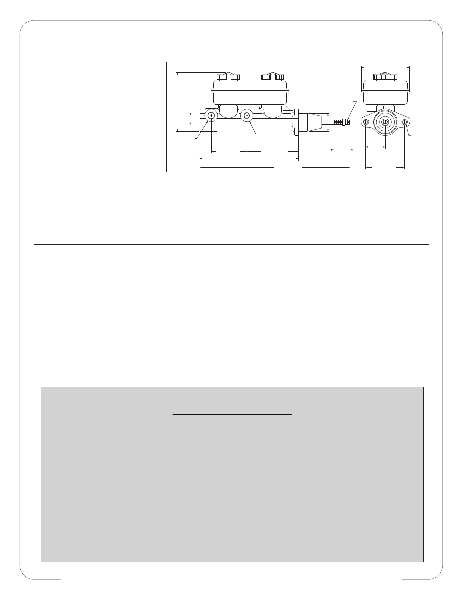
.34 (8,6)
DIA
MOUNT
HOLE
3/8-24 THREAD
1.50 (38,1)
DIA
1/2-20 THREAD
INVERTED FLARE
OUTLET "A"
9/16-20 THD
INVERTED
FLARE
OUTLET "B"
3.61 (91,7)
4.27 (108,5)
2.94 (74,7)
8.14 (206,8)
12.42 (315,5)
4.83
(122,7)
.55
(14,0)
1.35
(34,3)
STROKE
1.60
(40,6)
3.20 (81,3)
Tandem Master Cylinder, Mounting Dimensions
• Make sure pedal is firm: Hold firm pressure on pedal for several minutes, it should remain in position without
sinking. If pedal sinks toward floor, check system for fluid leaks. DO NOT drive vehicle if pedal does not stay firm
or can be pushed to the floor with normal pressure.
• At very low speed (2-5 mph) apply brakes hard several times while turning steering from full left to full right, repeat
several times. Remove the wheels and check that components are not touching, rubbing, or leaking.
• Carefully examine all brake components, brake lines, and fittings for leaks and interference.
• Make sure there is no interference with wheels or suspension components.
• Drive vehicle at low speed (15-20 mph) making moderate and hard stops. Brakes should feel normal and
positive. Again check for leaks and interference.
• Always test vehicle in a safe place where there is no danger to (or from) other people or vehicles.
• Always wear seat belts and make use of all safety equipment.
WARNING • DO NOT DRIVE ON UNTESTED BRAKES
BRAKES MUST BE TESTED AFTER INSTALLATION OR MAINTENANCE
MINIMUM TEST PROCEDURE