Assembly instructions – Wilwood W6A Big Brake Front Brake Kit User Manual
Page 4
Assembly Instructions
Assembly Instructions (numbers in parenthesis refer to the part list/diagram on the preceding page):
•The caliper mount bracket assembly (1) should be installed first with clean, dry threads on the mounting bolts. Install the bracket using
the original caliper mount bolts. The bracket must tighten squarely against the outboard side of the caliper mount bosses on the
spindle body. Inspect for interference from casting irregularities, machining ridges, burrs, etc. Use one thin shim (2) between the
bracket and spindle during initial trial fitting. Later, after the caliper, pad, and rotor alignment has been checked, and any necessary
shims have been put in place, the mount bolts should be coated with red Loctite
®
271 and torqued to 65 ft-lbs.
• Assemble the rotor (3) to the hat (4) with the bolts (6) and washers (5) provided in the
configuration pictured in Figure 1. Using an alternating sequence, apply red Loctite® 271 to
the threads and torque bolts to 155 in-lb. For an added measure of security, the bolts may be
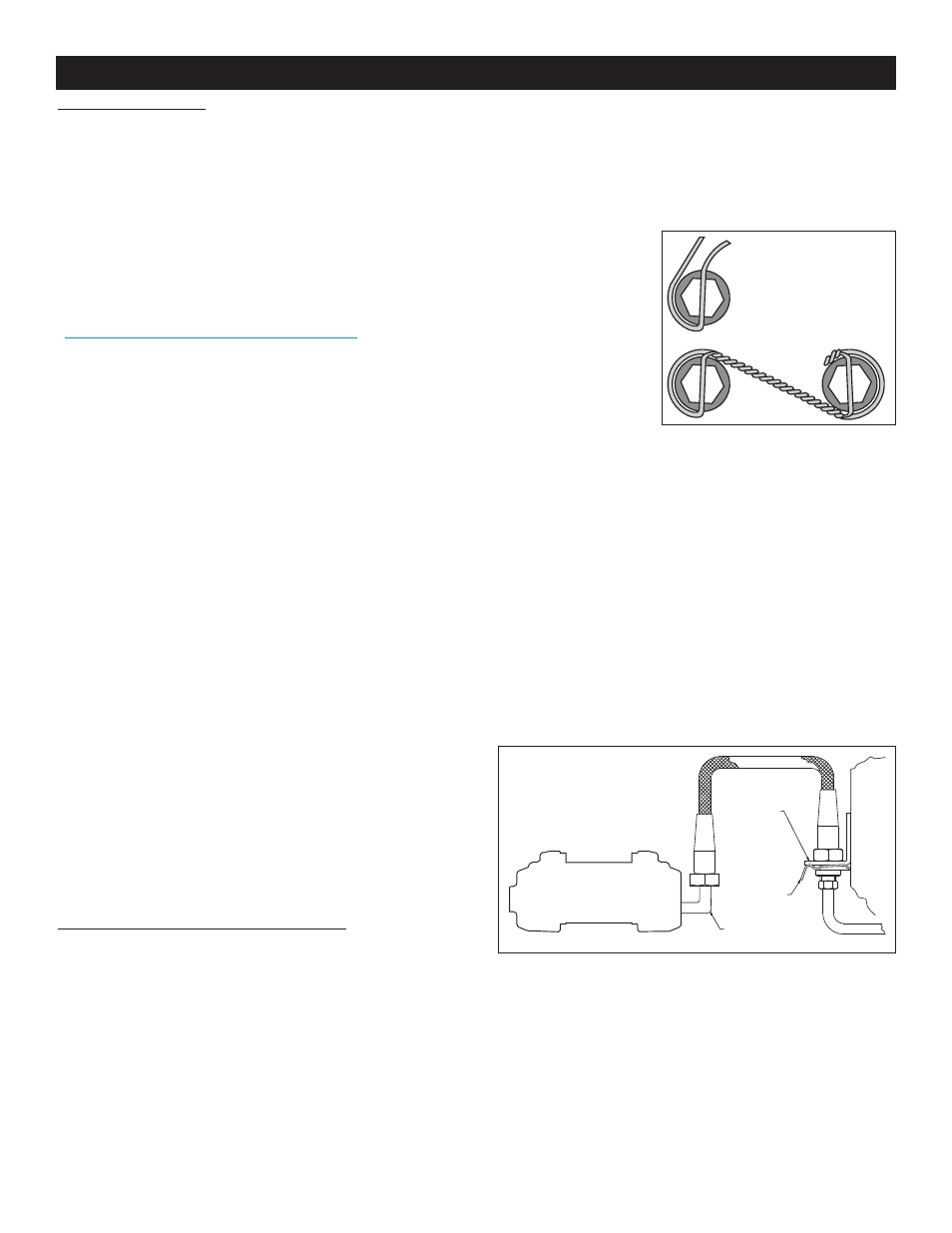
safety wired using standard 0.032 inch diameter stainless steel safety wire as shown in
Figure
3.
Please
refer
to
Wilwood’s
data
sheet
DS-386
(available
at
www.wilwood.com/Pdf/DataSheets/ds386.pdf
) for complete safety wire installation
instructions.
• Install the hat and rotor assembly onto the hub. Check to be sure the hat seats squarely
against the hub. The hub must be free from any rust, debris, casting burrs, machining
irregularities, etc. Use three lug nuts to hold the rotor and hat firmly against the hub during the
next phases of the installation and clearance checking procedures.
• Install one shim (11) over each stud (10) on the radial mount bracket (1). Slide the caliper (7)
in place over the studs and rotors and install the washer (9) and lock nut (8) to hold the caliper
in place. The caliper bleed screws should be pointing up. Snug the lock nuts (8) and check
that the rotor (3) is centered in the caliper (7). Add or subtract .029" shims (2) as necessary
between the mount bracket and the spindle to center the caliper.
• Remove the two caliper pad retaining pins from the caliper (1) by popping out the pin retaining clips and sliding out the pins. Slide the
brake pads (12) into place. They should install easily without interference. Check that the outside radius of the brake pad is aligned
with the outside diameter radius of the rotor face. Add or subtract shims (11) between the caliper and mount bracket to gain the proper
alignment. Reinstall the pad retaining pins and secure using the pin retaining clips
• Remove the lug nuts that were holding the hat in place. Install the wheel and torque the lug nuts to specification. Check to see that
the wheel rotates freely without interference.
• Once all clearances have been checked, remove the wheel,
caliper, hat, and rotor from the spindle and hub. Secure the caliper
mounting bracket (1) to the spindle using red Loctite
®
271.
Torque the bolts to 65 ft-lbs. Reinstall the hat and rotor
assembly and again use several lug nuts to hold it in place.
Lubricate caliper mounting studs and nuts with lightweight oil,
reinstall the caliper, torque the caliper nuts (8) to 47 ft-lbs.
Stock Brake Line Disassembly Instructions
•Unbolt banjo bolt from back of caliper.
•Unbolt rubber hose from hard line at frame.
•Pull the clip that holds the rubber hose to the bracket at the frame.
•Install Wilwood’s optional stainless steel braided flexline hose kit, part number 220-8176 (C-5) or 220-9100 (C-6) (NOT included in
kit), see Figure 4. Carefully route lines to prevent contact with moving suspension, brake or wheel components. Wilwood hose
kits are designed for use in many different vehicle applications and it is the installer's responsibility to properly route and ensure
adequate clearance and retention for brake hose components.
FLEXLINE
BRACKET
CLIP
90° ELBOW
FRAME
HARDLINE
WILWOOD
W6A CALIPER
Figure 4. Brake Line Diagram
BEGIN BY SLIDING THE 0.032"
DIAMETER WIRE THROUGH TWO OF
THE HOLES (LEFT) THAT ARE 180°
APART. TWIST THE WIRE AS
SHOWN (BELOW) USING SAFETY
WIRE PLIERS. NOW SLIDE ONE
WIRE THROUGH TWO OF THE
HOLES (180° APART) AND WRAP THE
OTHER WIRE AROUND THE BOLT.
TWIST THE WIRES TOGETHER TO
FORM A PIGTAIL. SEE DS-386 FOR
COMPLETE DETAILS.
Figure 3. Safety Wire Diagram
Page 4